
The proper separation of pipelines in dairy processing establishments is important to assure the safety of finished products. Improper separation of pipelines has been a factor in the outbreak of milkborne illness in the past.
A cross connection is a direct connection allowing one material to contaminate another. There needs to be a complete segregation of incompatible products such as raw materials and pasteurized or sterilized food products, cleaning products and food products, and waste materials or utility materials and food products.
For other applications (CIP (clean-in-place) supply lines and return line circuits used for CIP cleaning and mini-washes on tanks, lines, pasteurizers or other equipment that may be washed while connected to product lines containing milk products or potable water and lines for final rinse), use separate pipelines and vessels for incompatible products and establish effective physical breaks at connection points by at least one of the following arrangements: physical disconnecting of pipelines, double block and bleed valve arrangements, double seat (mix proof) valves, aseptic barriers, or other equally effective systems.
Flow diverter boards and “swing elbows” are traditionally used in dairy establishments to isolate cleaning circuits, preventing contamination of food products with cleaning solution; this provides a physical break (disconnection) between pipelines. The installation of any number of segregating valves (set of valves with no break to atmosphere) does not constitute a physical break, except in the following cases:
1. Double block and bleed valve arrangements for clean-in-place (CIP) cleaning
A double block and bleed valve arrangement with a self-draining (vent or leak port) break to atmosphere of at least the same hydraulic diameter as the largest supply line to the valves, located in between the two blocking valves, may be used to separate cleaning solutions from food products. The blocking valves act as a barrier to the product and the CIP solution, while the bleed line between them prevents the build-up of pressure and allows any leakage to be safely diverted away from the opposing valve seat.
- Valves:
- Use micro-switches or other sensors on valves used for the double block and bleed to signal that the valves are properly positioned for CIP cleaning.
- The valves move to the fail-safe blocking position with the bleed line open if air pressure or electrical power is removed from the valve solenoids.
- Use micro-switches or other sensors on valves used for the double block and bleed to signal that the valves are properly positioned for CIP cleaning.
- Vent or leak port:
- Ensure the design and installation of the vent/leak port permits the vent to clean properly by CIP methods.
- Clean the vent/leak port only when food products are isolated further upstream by another block and bleed valve set, flow board or swing elbow, or when food product has been removed from the system.
- Document procedures for the set-up, validation, maintenance, inspection and cleaning of this valve arrangement.
- Keep records demonstrating that the procedures are followed in daily operations.
2. Double seat (mix proof) valves for CIP cleaning
A double seat (mix proof) valve may be used to separate cleaning solutions from food products. This valve has two seats with a leakage chamber (vent or leak port) between them.
- Leakage chamber:
- Always keep the leak detect vent fully open to the atmosphere, unconnected and with no restrictions.
- Ensure leaks can be visibly detected.
- Ensure the leak detect tube has a hydraulic diameter greater than the hydraulic diameter of the supply.
- The hydraulic diameter can be defined as 4 × cross sectional area/perimeter.
- The supply cross sectional area is the perimeter of the seat multiplied by the travel of the seat lift, or where both seats are closed, it is the separate CIP supply port; the leak detect tube hydraulic diameter is the smallest of diameter in the leak tube.
- Valves:
- The valve's fail safe position is defined as closed.
- Use at least one microswitch or other sensor for the double seat (mix proof) valve to signal that the valve is properly positioned for CIP cleaning.
- Ensure the valve is closed (inactivated position) for CIP cleaning and only one seat lifter at a time can be activated.
- The seat lift travel is physically limited by design. Valve sequencing is done in such a manner that the two sides cannot open at the same time.
- Ensure there is no uncontrolled manual override of the system, and limited access to valve programming by unauthorized personnel/employees.
- Use testing, validation and documentation to ensure that valves function as intended.
- Clean the valve vent area:
- Perform individual seat lifts to allow some CIP solution to flush past and wash the product contact surface.
- Use external CIP connection to the cavity. The external CIP connection meets the hydraulic diameter criteria as outlined above.
- Document procedures for the set-up, validation, maintenance, inspection and cleaning of this valve arrangement.
- Keep records demonstrating that the procedures are followed in daily operations.
Double-seal type valves are not suitable for this application because they use only a single valve actuator and rod and are not designed to safely vent significant quantities of leakage away from an opposing valve seat.
3. Cleaning aseptic processing and packaging systems (APPS)
An aseptic barrier may be used to segregate cleaning solutions from sterilized milk products during CIP, mini-washes or pre-sterilization of an aseptic surge tank or aseptic filler and associated piping in the aseptic zone.
In the case of sterilized product in the aseptic zone of an aseptic processing and packaging system (APPS), an interlocked resistance thermal device (RTD) monitoring leakage in one or more steam blocks would take the place of the break to atmosphere and valve micro-switches described above.
- Aseptic barrier:
- Have one or more steam blocks.
- Install a resistance thermal device (RTD) or other suitable temperature sensor at the lowest level of the barrier to detect any fluid leakage into the barrier.
- Install an alarm or other appropriate system to alert the operator to the aseptic barrier failure.
- Take appropriate action as indicated by the scheduled process deviation procedure.
Verifying the absence of cross connections
- Use colour coding of pipelines on the plant schematic (or process and instrumentation drawing (PID)), the envelope method or other means to identify cross-connections in the piping between raw and pasteurized or sterilized product, cleaning products and food products, and waste materials or utility materials and food products.
- Look at the actual piping and valves in the establishment to verify that the schematic is accurate and that in actuality, no cross connections exist.
- Review cleaning and operating procedures to make sure that these procedures are not creating a cross-contamination risk.
- Verify that cleaning procedures and practices are being followed, especially in regards to CIP mini-washes done on pasteurizers, sterilizers, or other equipment where product could be contaminated by cleaning solutions through improper procedures or equipment hook-up.
- Maintain a listing of all cleaning chemicals and other non-food chemical products used at the establishment, and ensure that they are safe and suitable for use in dairy processing establishments.
Hydraulic diameter
The hydraulic diameter, dh, is used instead of the geometrical diameter for channels of non-circular shape and is defined as:
dh = 4 × cross-sectional area ÷ wetted perimeter
For different geometries dh becomes:
- Circular Tube: dh = 4 × π × d2 ÷ 4 ÷ π × d = d; dh = d
- Square Tube: dh = 4 × a2 ÷ 4× a = a; dh = a
- Two Concentric Tubes: dh = (4 × (π × D2 - π × d2) ÷ 4) ÷ (π × D + π × d) = D – d; dh = D – d
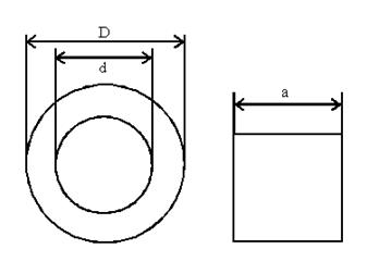
Description for image - Figure 1: Dimensions to calculate the hydraulic diameter
This figure illustrates the diameter of circular, square and concentric tubes that is used in equations to determine the hydraulic diameter of the tube.
d = diameter of circular tube or the inner diameter of concentric tubes.
a = the width of the square tube.
D = outer diameter of two concentric tubes, Hydraulic diameter equals four multiplied by the cross sectional area divided by the perimeter.
Hydraulic diameter equals four multiplied by the cross sectional area divided by the perimeter.
- Circular tube: Hydraulic diameter equals four multiplied by pi multiplied by the square of the diameter divided by four divided by pi multiplied by the diameter equals the diameter; Hydraulic diameter equals the diameter.
- Square tube: Hydraulic diameter equals four multiplied by the square of the length divided by four multiplied by the length equals the length; Hydraulic diameter equals the length.
- Two concentric tubes: Hydraulic diameter equals pi multiplied by the square of the outer diameter minus the product of pi multiplied by the square of the inner diameter the total of which is divided by four and then divided by the total of pi multiplied by the outer diameter plus the product of pi multiplied by the inner diameter equals the outer diameter minus the inner diameter; Hydraulic diameter equals outer diameter minus inner diameter.
Hydraulic diameter and flow resistance
To compare runners of different shapes, use the hydraulic diameter, which is an index of flow resistance. The higher the hydraulic diameter, the lower the flow resistance. Hydraulic diameter can be defined as:
dh = 4A ÷ P
Where,
dh= hydraulic diameter
A = cross section area
P = perimeter

Description for image - Illustration of how to use the hydraulic diameter to compare different runner shapes
This image shows the hydraulic diameter for a hexagon (0.9523), a half-oval (0.9116), a square (0.8862), a trapezoid (0.8771), a half-circle (0.8642), a short rectangle (0.8356) and a long rectangle (0.7090).