
On this page
- Introduction
- Record keeping
- Operation, installation and design specifications of a meter based timing system
- References
Introduction
The magnetic flow meter is used to measure the flow rate in high temperature short time (HTST), higher heat shorter time (HHST), and aseptic processing and packaging systems (APPS). It is essentially a short piece of tubing (approximately 25 cm (10 inches) long) surrounded by a housing, inside of which are located coils which generate a magnetic field. 2 stainless steel electrodes about a 1/4 inch in diameter protrude approximately 1 inch into the Teflon lined tube and provide the contact points for the fluid (a conductor) passing through the magnetic field. These electrodes pick up a signal from the moving fluid and activate a transmitter. The signal is sent to other instrumentation where it is recorded and acted upon.
Magnetic flow meters may be advantageous over other types of flow control devices since they:
- provide no obstruction to the fluid
- contain no moving parts
- remain unaffected by changes in conductivity, viscosity, density or temperature
- produce negligible pressure loss
- do not require purging
- may be installed at nearly any point along a pipeline
Magnetic flow meters do nothing but measure flow. Other components regulate the flow.
Meter based timing meter components that are used as a replacement for a flow control device on critical process systems (HTST, HHST, APPS) must be suitable for this purpose.
- The U.S. Food and Drug Administration maintains the Index of Memoranda of Milk Ordinance Equipment Compliance (M-b) which lists components they have reviewed and found acceptable.
A meter based timing system (MBTS) used as a flow control device within a critical process system consists of the following components:
- centrifugal or positive displacement timing pump
- magnetic flow meter
- product check valve or normally closed air operated valve
- flow recorder with event pen
- high flow alarm
- low flow/loss of signal alarm
- flow control (with operator interfaced flow controller):
- control valve or alternating current (AC) variable frequency drive
Record keeping
In a Preventive Control Plan (PCP), it is important to maintain and keep records of activities which demonstrate that the PCP is implemented and working effectively. Records can be in either a hard copy or electronic format. Refer to Record keeping for your preventive control plan for additional information.
Operation, installation and design specifications of a meter based timing system
AC Variable frequency drive system
Ensure the operation, installation and design specifications of a MBTS with an AC variable frequency drive system meets the following:
- The systems have a suitable flow recorder capable of recording flow at the high flow alarm set point and also at least 5 gallons (19 litres) per minute higher than the high flow alarm setting. The flow recorder has an event or divert pen which records the duration of the alarm condition.
- A high flow alarm with an adjustable set point is installed within the system which will automatically cause the flow diversion device to be moved to the divert position whenever excessive flow rate causes the product holding time to be less than the legal holding time for the pasteurization process being used. Test and seal this adjustment.
- A low flow or loss of signal alarm is installed with the system which will automatically cause the flow diversion device to be moved to the divert position whenever there is a loss of signal from the meter or the flow rate is below 5% of the maximum signal alarm set point. See Computerized systems logic diagrams, Figure 1 in Appendix D.
- When the legal flow rate has been re-established following an excessive flow rate, a time delay is instituted which will prevent the flow diversion device from assuming the forward flow position until at least a 15 second (milk) HTST or 25 second (frozen dessert mix) HTST or 1 second (APPS and HHST), continuous legal flow has been re-established. Test the time delay and, if it is of the adjustable type, seal.
- A sanitary product check valve or normally closed air operated valve is installed in the system to prevent positive pressure in the raw milk side of the regenerator whenever a power failure or shut down occurs. The check valve or normally closed air operated valve is placed between the magnetic flow meter and the start of the holding tube.
- Ensure the placement of the individual components in the system meets the following conditions:
- The AC variable frequency controlled centrifugal or positive displacement pump is located downstream from the raw milk regenerator section if a regenerator is used.
- The magnetic flow meter is placed downstream from the AC variable frequency centrifugal or positive displacement pump. There are no intervening components in the system other than normal sanitary piping with no valves or control devices between them.
- Both the AC variable frequency centrifugal or positive displacement pump and the magnetic flow meter are located upstream from the holding tube.
- All other flow promoting devices such as booster pumps, stuffing pumps, separators, clarifiers and homogenizers, as well as the AC variable frequency centrifugal or positive displacement pump, are inter-wired with the flow diversion device so that they may run and produce flow through the system only when the flow diversion device is in the fully diverted or fully forward flow position when in product run mode. Separators or clarifiers which continue to run after power is shut off to them are automatically valved out of the system with fail safe valves so that they are incapable of producing flow during this period and when the flow diversion device is in the diverted flow position. In the case of APPS using indirect or direct heating systems, the product divert device will remain in the divert position when the flow rate is higher that the specified value in the scheduled process.
- No product enters or leaves the system (for example, cream or skim from a separator or other product components) between the AC variable frequency centrifugal or positive displacement pump and the flow diversion device.
- The magnetic flow meter is installed so that the product has contact with both electrodes at all times when there is flow through the system. This is most easily accomplished by mounting the flow tube of the magnetic flow meter in a vertical position with the direction of flow from the bottom to the top. However, horizontal mounting is acceptable when other precautions are taken to assure that both electrodes are in contact with product. They should not be mounted on a high horizontal line which may be only partially full and thereby trap air.
- The magnetic flow meter is piped so that at least 10 pipe diameters of straight pipe exists upstream and downstream from the centre of the meter before any elbow or change of direction takes place.
- When a regenerator is used with these systems, it probably will be necessary to bypass the regenerator during start up and when the flow diversion device is in the diverted flow position. Care should be taken in the design of such bypass systems to assure that a dead end does not exist. A dead end could allow product to remain at ambient temperature for long periods of time and allow bacterial growth in the product. Caution should also be observed with such bypass systems and any valves used in them so that raw milk product will not be trapped under pressure in the raw regenerator plates and not have free drainage back to the constant level tank when shutdown occurs.
- Most such systems will use a dual stem flow diversion device and will be using the AC variable frequency centrifugal pump during the CIP cleaning cycle. When switching to the CIP position, the flow diversion device moves to the divert position and remains in the diverted flow position for at least 10 minutes of the CIP cycle regardless of temperature and the booster pump cannot run during the first 10 minutes of the CIP cycle. Once the CIP cycle has been activated the operator has 10 minutes to switch back to "process mode".
- When public health computers or programmable logic controllers are used with these systems, they are installed so that no public health controls are under the computer or programmable logic controller during the product run operations.
- The computer or programmable logic controller may control the speed of the AC variable frequency centrifugal or positive displacement pump provided the high flow alarm is set and sealed to provide for diversion of the flow diversion device whenever the design flow rate is exceeded.
- Test all controls at the recommended frequency. Where adjustment or changes can be made to these devices or controls, apply appropriate seals so that changes cannot be made without detection.
- Upon initial installation and at the recommended frequency, test all MBTS for holding times.
- Perform tests in forward flow (above legal temperature) and diverted flow (below legal temperature).
- At least 6 consecutive results should be within a 0.5 second range of each other.
- If 6 consecutive times within a 0.5 second range cannot be obtained in forward and diverted flow, contact the designer of the installation to correct the problem before using the system.
- Perform all timing tests in accordance with the procedures outlined in Critical process test procedures.
- Design and install the system so that the timing tests can be conducted in automatic mode in both forward and diverted flow.
- Automatic mode means that the flow through the system is under control of the magnetic flow meter, and the system controls will automatically vary the speed of the centrifugal pump to maintain a constant flow rate through the system.
- In automatic mode, the set point of the automatically controlled flow rate will need to be manually adjustable.
Control valve system
Ensure the operation, installation and placement specifications for a MBTS using a single speed centrifugal or positive displacement pump and control valve meets the following:
- The systems have a suitable flow recorder capable of recording flow at the high flow alarm set point and also at least 5 gallons (19 litres) per minute higher than the high flow alarm setting. The flow recorder has an event or divert pen which records the duration of the alarm condition.
- A high flow alarm with an adjustable set point is installed within the system which will automatically cause the flow diversion device to be moved to the divert position whenever excessive flow rate causes the product holding time to be less than the legal holding time for the pasteurization process being used. Test and seal the adjustment.
- A low flow or loss of signal alarm is installed with the system which will automatically cause the flow diversion device to be moved to the divert position whenever there is a loss of signal from the meter or the flow rate is below 5% of the maximum signal alarm set point. See Computerized systems logic diagrams, Figure 1 in Appendix D.
- When the legal flow rate has been re-established following an excessive flow rate, a time delay is instituted which will prevent the flow diversion device from assuming the forward flow position until a least a 15 second (milk) HTST or 25 second (frozen dessert mix) HTST or 1 second (APPS and HHST), continuous legal flow has been re-established. Test the time delay and, if it is of the adjustable type, seal.
- A sanitary product check valve or normally closed air operated valve is installed in the system to prevent positive pressure in the raw milk side of the regenerator whenever a power failure or shut down occurs. The check valve or normally closed air operated valve is placed between the magnetic flow meter and the start of the holding tube.
- Ensure the placement of the individual components in the system meet the following conditions:
- The centrifugal or positive displacement pump is located downstream from the raw milk section if a regenerator is used.
- The magnetic flow meter is placed downstream from the centrifugal or positive displacement pump. There are no intervening components in the system other than normal sanitary piping with no valves or control devices between them.
- The control valve is placed downstream from the magnetic flow meter and upstream from the start of the holding tube.
- The centrifugal or positive displacement pump, the magnetic flow meter and the control valve are located upstream from the holding tube.
- All other flow promoting devices such as booster pumps, stuffer pumps, separators, clarifiers and homogenizers, as well as the centrifugal or positive displacement pump, are inter-wired with the flow diversion device so that they may run and produce flow through the system only when the flow diversion device is in the fully diverted or safe forward position when in product run mode. Separators or clarifiers which continue to run after power is shut off to them are automatically valved out of the system with fail safe valves so that they are incapable of producing flow during this period and when the flow diversion device is in the diverted flow position. In the case of APPS using indirect or direct heating systems, the product divert device will remain in the divert position when the flow rate is higher that the specified value in the scheduled process.
- No product enters or leaves the system (for example, cream or skim from a separator or other product components) between the centrifugal or positive displacement pump and the flow diversion device.
- The magnetic flow meter is installed so that the product has contact with both electrodes at all times when there is flow through the system. This is most easily accomplished by mounting the flow tube of the magnetic flow meter in a vertical position with the direction of flow from the bottom to the top. However, horizontal mounting is acceptable when other precautions are taken to assure that both electrodes are in contact with product. They should not be mounted on a high horizontal line which may be only partially full and thereby trap air.
- The magnetic flow meter is piped so that at least 10 pipe diameters of straight pipe exists upstream and downstream from the centre of the meter before any elbow or change of direction takes place.
- When a regenerator is used with these systems, it may be necessary to bypass the regenerator during start up and when the flow diversion device is in the diverted flow position. Care should be taken in the design of such bypass systems to assure that a dead end does not exist. A dead end could allow product to remain at ambient temperature for long periods of time and allow bacterial growth in the product. Caution should also be observed with such bypass systems and any valves used in them so that raw milk product will not be trapped under pressure in the raw regenerator plates and not have free drainage back to the constant level tank when shutdown occurs.
- Most systems will use a dual stem flow diversion device and will be using the AC variable frequency centrifugal pump during the CIP cleaning cycle. When switching to the CIP position, the flow diversion device moves to the divert position and remains in the diverted flow position for at least 10 minutes of the CIP cycle regardless of temperature and the booster pump cannot run during the first 10 minutes of the CIP cycle. Once the CIP cycle has been activated the operator has 10 minutes to switch back to "process mode".
- When public health computers or programmable logic controllers are used with these systems, they are installed so that no public health controls are under the computer or programmable logic controller during the product run operations.
- The computer or programmable logic controller may control the speed of the AC variable frequency centrifugal or positive displacement pump provided the high flow alarm is set and sealed to provide for diversion of the flow diversion device whenever the design flow rate is exceeded.
- Test all controls at the recommended frequency. Where adjustment or changes can be made to these devices or controls, apply appropriate seals so that changes cannot be made without detection.
- Upon initial installation and at the recommended frequency, test all MBTS for holding times.
- Perform tests in forward flow (above legal temperature) and diverted flow (below legal temperature).
- At least 6 consecutive results should be within a 0.5 second range of each other.
- If 6 consecutive times within a 0.5 second range cannot be obtained in forward and diverted flow, contact the designer of the installation to correct the problem before using the system. Perform all timing tests in accordance with the procedures outlined in Critical process test procedures.
- Design and install the system so that the timing tests can be conducted in automatic mode in both forward and diverted flow.
- Automatic mode means that the flow through the system is under control of the magnetic flow meter, and the system controls will automatically vary the speed of the centrifugal pump to maintain a constant flow rate through the system.
- In automatic mode, the set point of the automatically controlled flow rate will need to be manually adjustable.
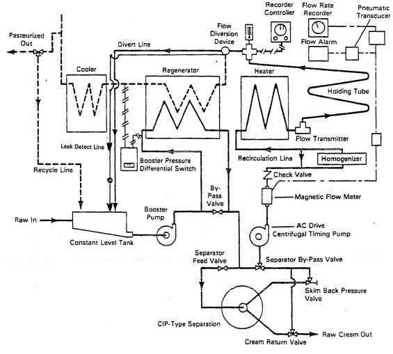
Description for HTST system with a magnetic flow meter using an alternating-current variable speed centrifugal pump.
- The raw milk starts at the raw in and goes into the constant level tank. From here material passes through the booster pump, passes the booster pressure differential switch and through the regenerator. It flows through the separator feed valve, and then goes into the clean-in-place-type separation.
- From here it can go 1 of 2 ways:
- past the cream return valve and then exists via the raw cream out valve, or
- past the skim back pressure valve, to the separator by-pass valve, and then through the alternating current drive centrifugal timing pump
- it then flows through the magnetic flow meter, which consists of the flow rate recorder, the flow alarm and the pneumatic transducer
- the material then passes through the check valve, the homogenizer, the recirculation line and into the heater, then through the flow transmitter and through the holding tube, passing the recorder controller
- From the flow diversion device, the material can go 1 of 2 ways:
- through the regenerator, the cooler and then exits through the pasteurized out, or
- through the regenerator, the cooler and then down the recycle line to the constant level tank
- The second route is for the material to flow through the divert line, and into the constant level tank.
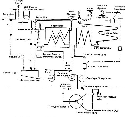
Description for HTST system with magnetic flow meter using a constant speed centrifugal pump and a control valve.
- Starting with raw milk coming in through the raw in and into the constant level tank, the material goes into the booster pump, past the booster pressure differential switch, through the regenerator, and through the separator feed pump. It passes through CIP-type separation and then goes 1 of 2 ways.
- through the cream return valve and to exit through the raw cream out, or
- through the skim back pressure valve, to the separator by-pass valve, and then through the centrifugal timing pump
- it then goes through the magnetic flow meter, which consists of a pneumatic transducer, a flow rate recorder, and a flow alarm
- it then flows through the flow control valve, the heater, the flow transmitter and the holding tube, and then past the safety thermal limit recorder, through the flow diversion device
- it can then either flow through the regenerator, through the vacuum breaker or the back pressure controller and valve, and exit via the pasteurized out, or it can flow through the recycle line to the constant level tank
- The other route from the flow diversion device is for material to flow through the divert line and into the constant level tank.