
On this page
- Introduction and use of test procedure
- Thermometers
- Test 1: Indicating thermometers - temperature accuracy
- Test 2: Indicating thermometers - thermometric response
- Test 3: Recording thermometers - check against indicating thermometer
- Test 4: Recording thermometer - time accuracy
- Test 5: Recording thermometer - temperature accuracy
- Test 6: Milk-flow controls - milk temperatures at cut-in and cut-out
- Test 7: Safety thermal limit recorder - thermometric response
- Holding time
- Flow diversion device (FDD)
- Test 10: Leakage past valve seat(s)
- Test 11: Operation of valve stem(s)
- Test 12: Device assembly - single stem device
- Test 13: Device assembly - dual stem device
- Test 14: Manual diversion
- Test 15: Response time
- Test 16: Valve flush time delay
- Test 17: Time delay interlock with flow control device (FCD)
- Test 18: Clean-in-place (CIP) time delay relay
- Pressure differential
- Test 19: Pinholes check - dye re-circulation procedure
- Test 20: Pressure differential controller
- Test 21: Pressure gauges - displays
- Test 22: Booster pumps - inter-wired with flow diversion device (FDD)
- Test 23: Booster pumps - inter-wired with pressure differential controller
- Test 24: Booster pumps - inter-wired with flow control device (timing pump, metering pump)
- Meter based timing system
- Test 25: High flow alarm
- Test 26: Loss of signal alarm
- Test 27: Flow cut-in and cut-out
- Test 28: Time delay relay (flow recorder)
- Test 29: Thermal limit controller for control-sequence logic
- Test 30: Setting of control switches for product pressure in the holding tube
- Test 31: Setting of control switches for differential pressure across the injector
- Other
- Appendices
Introduction and use of test procedures
A pasteurization system is made up of a pasteurizer and an intricate grouping of components all working together to ensure that every particle of product has been properly pasteurized. The tests described in this document are designed to ensure that the components are functioning properly. The failure of any component to carry out the function it was designed and installed to do could result in unpasteurized product.
- Test the critical processes (for example, high temperature short time (HTST), batch pasteurizer, aseptic processing and packaging system (APPS) and higher heat shorter time (HHST)) according to the test procedures found in this document1.
- This testing can be done by trained establishment personnel or a reliable third party.
- A summary of the results of the testing can be recorded on the test procedures form in Appendix 2: Test procedures form.
- Designate a person (ideally someone other than the operator of the pasteurizer) to review the results on a timely basis to ensure accuracy of testing and that corrective action was taken both on the equipment and on the product, if necessary.
- Develop a written program for the routine, planned testing of the critical process equipment and controls, including procedures that outline what tests are being performed, frequency, who is responsible, verification procedures, corrective action and records kept.
- In addition, perform these equipment tests any time there are alterations or new installations to the critical processes in order to evaluate the effectiveness of the changes and the impact on the system.
- For example: adding a control mechanism in the cooling section; installing a proximity switch.
Thermometers
Test 1: Indicating thermometers - temperature accuracy
Application:
- Pasteurization and airspace indicating thermometers.
- Applies to HTST, batch, APPS and HHST systems.
Frequency:
- Upon installation and once every 6 months thereafter.
- Whenever the seal on a digital sensor or a digital control box has been broken and the reason for the breaking of the seal may have an effect on the sensing element.
Criteria:
- Pasteurization indicating thermometer: verify accuracy within 0.25ºC (0.5ºF) in a specified scale range.
- Airspace indicating thermometer: verify accuracy within 0.5ºC (1ºF) in a specified scale range.
Apparatus:
- A certified test thermometer meeting the specifications of Appendix 1: Testing apparatus specifications
- Water, oil or other suitable media bath and agitator
- Suitable means of heating media bath
- Indicating thermometer to be tested
Method:
- Verify both the indicating and test thermometers are exposed to water, oil or other suitable media bath of uniform temperature.
- Compare the indicating thermometer reading to the reading of the test thermometer.
Procedure:
- Bring the media bath temperature to within a range of 2ºC of the pasteurization (diversion) temperature, airspace temperature or aseptic processing temperature.
- Maintain rapid agitation throughout the test.
- Insert the indicating and test thermometer to indicated immersion point during the test. Hold the indicating and certified thermometer for five minutes, or two minutes for electronic recording thermometers, before reading.
- Compare both thermometer readings at the temperature reading within the test range and record results and thermometer identification.
- Repeat the test 3 times.
Corrective action:
- When the indicating thermometer differs from the test thermometer by more than 0.25°C (0.5°F) and the airspace thermometer by more than 0.5 ºC (1°F), adjust the scale plate of the indicating thermometer to agree with the test thermometer.
- Retest the thermometer after adjustment.
Note
The above procedure applies only to recording thermometers used for pasteurization. All other recording thermometers used in the establishment should be tested according to the manufacturer's recommendations.
Test 2: Indicating thermometers - thermometric response
Application:
- Pasteurization indicating thermometer.
- Applies to HTST systems.
Frequency:
- Upon installation and once every 6 months thereafter.
- Whenever the indicating thermometer has been repaired and/or replaced.
- Whenever the seal on the indicating thermometer is broken.
Criteria:
- Verify the indicating thermometer moves through a 7ºC (12ºF) range in no more than 4 seconds.
Apparatus:
- Test thermometer
- Stopwatch
- Water, oil or other suitable media bath and agitator
- Suitable means for heating media bath
- Indicating thermometer from pasteurizer
- Bucket of ice water
Method:
- Measure the time required for the reading of the thermometer being tested to increase 7ºC (12ºF) through a specified temperature range (temperature range must include pasteurization or treatment temperature).
- The temperature used in the media bath will depend upon the scale range of the thermometer to be tested.
Procedure:
- Immerse the indicating thermometer in media bath held at a temperature at least 11ºC (19ºF) higher than the minimum scale reading on the indicating thermometer. The bath temperature should be higher than the maximum pasteurization temperature for which the thermometer is used.
- Immerse indicating thermometer in bucket of ice water for 10 seconds to cool it.
Note: Continuous vigorous agitation of media baths during the performance of steps 3, 4 and 5 is required. Do not allow the elapsed time between end of step 1, and beginning of step 3 to exceed 15 seconds so that the hot water does not cool significantly. - Insert indicating thermometer in hot media bath to proper bulb immersion depth.
- Start stopwatch when indicating thermometer reads 11ºC (19ºF) below bath temperature.
- Stop stopwatch when indicating thermometer reads 4ºC (7ºF) below bath temperature.
- Record the thermometric response time (must be less than 4 seconds).
- Repeat the test three times.
- Record the results.
Example: For a thermometer used at pasteurization temperature set points of 71.7 and 74.4ºC (161 and 166ºF), a media bath at a temperature of 78.3ºC (173ºF) could be used. 11ºC (19ºF) lower than 78.3ºC (173ºF) media bath would be 67.3ºC (154ºF); 4ºC (7ºF) lower than 78.3ºC (173ºF) media bath would be 74.3ºC (166ºF). Hence, after immersing the thermometer which has been previously cooled, in the 78.3ºC bath (173ºF), the stopwatch is started when thermometer reads 67.3ºC (154ºF) and stopped when it reads 74.3ºC (166ºF).
Note
The test included the pasteurization temperature of 71.7 and 74.4ºC (161 and 166ºF).
Corrective action:
- If the response time exceeds 4 seconds, repair or replace the thermometer.
- Do not operate the pasteurization system until the cause of this failure has been corrected
Test 3: Recording thermometers - check against indicating thermometer
Application:
- All recording and controller thermometers used to record milk temperatures during pasteurization.
- Applies to HTST, batch, APPS and HHST systems.
Frequency:
- Upon installation, once a year (6 months for APPS), and daily by the operator.
Criteria:
- Verify the recording thermometer does not read higher than corresponding indicating thermometer.
Apparatus:
- Certified or calibrated indicating thermometer
- Water, oil or other suitable media bath and agitator
- Suitable means to heat the media bath
Method:
- Compare the reading of the recording thermometer with that of the indicating thermometer at a time when both are exposed to milk at a stabilized pasteurization temperature, while the pasteurization system is operating and both thermometers are installed in their normal location in the temperature sensing chamber.
Procedure A: annual test
- Place the indicating or certified thermometer and recorder probe in a circulating media bath at processing temperature. Stabilize for five minutes (two minutes for electronic recording thermometers).
- Read the indicating and recording thermometer. Record the results.
- Adjust the recording pen to the same as the indicating thermometer if needed.
Procedure B: daily test
- Read the indicating thermometer when the milk is at a stabilized temperature for 5 minutes (two minutes for electronic recording thermometers).
- Immediately inscribe a line using permanent ink on the recording thermometer chart that intersects the recording temperature arc at the pen location.
- Record on the chart the indicating thermometer temperature and initials of the operator or person performing the test.
- Record results.
Corrective action:
- If the mercury-activated thermometer or recorder-controller thermometer reads higher than the indicating thermometer, adjust the pen or temperature adjusting mechanism.
- Re-test the thermometer after adjustment.
- If the digital recording thermometer or recorder-controller thermometer reads higher than the indicating thermometer, adjust the recording temperature arm to agree with the indicating thermometer if the recorder-controller arm is equipped with an adjustment.
- Re-test the thermometer after adjustment.
- In cases where the recorder-controller thermometer arm cannot be adjusted (i.e. the recorder chart is digitally transcribed and there is no recorder arm), recalibrate the recording thermometer and adjust it using Procedure A.
- Document the details of the recorder-controller deviation and the corrective action.
Note
The above procedure applies only to recording thermometers used for pasteurization. All other recording thermometers should be calibrated according to the manufacturer's recommendations.
Test 4: Recording thermometer - time accuracy
Application:
- All recording and recorder/controller thermometers used to record time of pasteurization.
- Applies to HTST, batch, APPS and HHST systems.
Frequency:
- Upon installation and at least once a year (6 months for APPS) thereafter.
Criteria:
- The recorded time of pasteurization does not exceed true elapsed time.
Apparatus:
- Stopwatch.
Method:
- Comparison of the recorded time over a period of not less than 30 minutes with a stopwatch of known accuracy.
- For recorders utilizing electric clocks, check cycle on face plate of clock with known cycle; observe that clock is in operating condition.
Procedure:
- Determine if chart is appropriate to recorder. Verify that mechanism to grip and perforate chart paper is operational.
- Mark a reference point on the backplate of the recorder at the outer circumference of the chart paper.
- With the chart paper removed from the recorder, inscribe a reference mark at the outer edge of the chart, lined up with any printed hour time line.
- Install chart in the recorder with reference mark on chart lined up exactly with reference mark on back plate. Secure in place.
- Start stopwatch.
- At the end of 30 minutes by stopwatch, inscribe a second reference mark on the chart paper exactly opposite the backplate reference mark.
- Stop the stopwatch.
- Compare the time recorded on the chart with the true elapsed time from the stopwatch.
- For electric clocks, remove face plate; compare cycle specification on face plate with current cycle utilized.
- Enter finding on chart and initial.
- Record results.
Corrective action:
- If recorded time is incorrect, adjust the clock or have it repaired.
Note
The above procedure applies only to recording thermometers used for pasteurization. All other recording thermometers used in the establishment should be tested according to the manufacturer's recommendations.
Test 5: Recording thermometer - temperature accuracy
Application:
- All recording and recorder/controller thermometers used to record milk temperatures during pasteurization.
- Applies to HTST, batch, APPS and HHST systems
Frequency:
- Upon installation, at least once a year (6 months for APPS) and whenever recording pen-arm setting requires frequent adjustment.
Criteria:
- Accuracy within 0.5ºC (1ºF), in specified scale range.
- Batch pasteurizers used solely for thirty (30) minute pasteurization of milk or milk products at processing temperatures above 71°C, the recording thermometers shall be accurate to within 1°C (2° F).
Apparatus:
- Verified pasteurizer indicating thermometer.
- Three water, oil or other suitable media baths and agitator.
- Suitable means for heating the media bath.
- Ice.
Method:
- The testing of a recording thermometer for temperature accuracy involves the determination of whether or not the temperature pen-arm will return to within 0.5ºC (1ºF) or within 1ºC (2° F) as provided above, of its previous setting after exposure to boiling water and melting ice.
Procedure:
- Heat a container of water to pasteurization temperature.
- Adjust the recording pen to read exactly as the previously tested indicating thermometer after a stabilization period of 5 minutes (2 minutes for electronic recording thermometers) at pasteurization temperature. Rapidly agitate the media throughout the stabilization period.
- Prepare one media bath by heating to the boiling point. Maintain temperature. Prepare a second bath with melting ice. Place baths within working distance of the recorder sensing element.
- Immerse the sensing element of recorder in boiling media for not less than 5 minutes (2 minutes for electronic recording thermometers).
- Remove the sensing element from the boiling media and immerse it in the media heated to pasteurization temperature. Allow a 5 minute (2 minutes for electronic recording thermometers) stabilization period for both indicating or certified and recording thermometers. The two readings must be within 0.5ºC (1ºF) or 1ºC (2° F) as provided above. Rapidly agitate the media throughout the stabilization period.
- Remove sensing element from the bath at operating temperatures and immerse in melting ice for not less than 5 minutes (2 minutes for electronic recording thermometers).
- Remove sensing element from ice water and immerse in water at pasteurization temperature. Allow 5 minute (2 minutes for electronic recording thermometers) stabilization period for both indicating or certified and recording thermometers. The two readings must be within ±0.5ºC (1ºF) or 1ºC (2° F) as provided above. Rapidly agitate the media bath throughout the stabilization period.
- Record results.
Corrective action:
- If the recording pen does not return to 0.5°C (1°F) or 1ºC (2°F) as provided above, of indicating thermometer reading, repair the recording thermometer or replace it as necessary.
Note
The above procedure applies only to recording thermometers used for pasteurization. All other recording thermometers used in the establishment should be tested according to the manufacturer's recommendations.
Test 6: Milk-flow controls - milk temperatures at cut-in and cut-out
A: Installation and inspection test
Application:
- All safety thermal limit recorders used in connection with HTST pasteurizers.
Frequency:
- Upon installation and once every 6 months thereafter.
- Whenever the seal on the sensing element of the recorder-controller is broken and the reason for the breaking of the seal may have an effect on the sensing element.
Criteria:
- No forward flow until pasteurization temperature has been reached.
- Flow is diverted before temperature drops below minimum pasteurization temperature.
- Cut-in temperature is higher than cut-out temperature.
Apparatus:
- Water, oil or other suitable media bath and agitator.
- Indicating or certified test thermometer meeting the specifications of Appendix 1: Testing apparatus specifications.
- Water bottle.
Method:
- Observe the actual temperature of the indicating thermometer at the instant forward flow starts (cut-in) and stops (cut-out).
Procedure 1: Cut-in temperature
- While the media in the bath is completely flooding the sensing element of the safety thermal limit recorder and the indicating or certified thermometer, increase the heat in the bath gradually at a rate not exceeding 0.5ºC (1ºF) every 30 seconds. Rapidly agitate the media bath throughout the test.
- Observe the indicating or certified thermometer reading at the instant the flow diversion device (FDD) starts to move.
- Observe that the frequency pen reading is synchronized with the recording pen on the same reference arc.
- Record the indicating or certified thermometer reading.
Procedure 2: Cut-out temperature
- After the cut-in temperature has been determined and while the media is above the cut-in temperature, allow the media to cool slowly at a rate not exceeding 0.5ºC (1ºF) per 30 seconds. Cool media in a bottle may be used if necessary.
- Observe indicating or certified thermometer reading at the instant forward flow stops.
- Record the indicating or certified thermometer reading.
B: Daily test
Application:
- All safety thermal limit recorders used in connection with HTST pasteurizers.
Frequency:
- Daily by the operator, whenever a new set-point is selected on a multiple temperature divert unit and whenever the seal on the recorder/controller is broken.
Criteria:
- No forward flow until pasteurization temperature has been reached.
- Flow is diverted before temperature drops below minimum pasteurization temperature.
- Cut-in temperature is higher than cut-out temperature.
Apparatus:
- None.
Method:
- Observe the actual temperature of the indicating thermometer at the instant forward flow starts (cut-in) and stops (cut-out).
Procedure 1: Cut-in temperature
- With the system operating and while milk or water is completely flooding the sensing element of the safety thermal limit recorder and the indicating thermometer within the sensing chamber, increase the heat gradually so as to raise the temperature of the water or milk at a rate not exceeding 0.5ºC (1ºF) every 30 seconds.
- Observe the indicating thermometer reading at the instant the FDD begins to move.
- Observe that the frequency pen reading is synchronized with the recording pen on the same reference arc.
- Record the indicating thermometer reading on the recorder chart; inscribe initials.
Procedure 2: cut-out temperature
- After the cut-in temperature has been determined and while the milk or water is above the cut-in temperature, allow the milk or water to cool slowly at a rate not exceeding 0.5ºC (1ºF) per 30 seconds.
- Observe indicating thermometer reading at the instant forward flow stops.
- Record the indicating thermometer reading on the recorder chart; inscribe initials.
Corrective action:
- If the reading is below the minimum pasteurization temperature, adjust the cut-in and cut-out mechanism and/or the differential temperature mechanism to obtain proper cut-in and cut-out temperatures by repeated tests.
Test 6.1: Milk-flow controls - milk temperatures - cut-in and cut-out HHST pasteurizers and APPS using indirect heating
Application:
- All HHST pasteurizers and APPS using indirect heating.
- When testing aseptic processing systems, the "product divert system" or product divert valve or acceptable control system may be substituted for the FDD when it is referenced in this test.
Frequency:
- Upon installation, and every 6 months thereafter and whenever the thermal controller seal is broken and the reason for the breaking of the seal may have an effect on the sensing element.
Criteria:
- No forward flow unless pasteurization or aseptic processing temperature has been achieved.
- Product flow diverted at a temperature lower than the chosen pasteurization or aseptic processing standard (i.e. is established by the scheduled process, where Fo = 3.0 as a minimum).
Apparatus:
- Oil bath (above boiling point).
Method:
- Observe the actual temperature in the constant temperature bath at which the two sensing elements (holding tube and FDD) signal for forward flow (cut-in) and diverted flow (cut-out).
Procedure 1: cut-in temperature
- Wire the test lamp in series with the control contacts of the sensing element (holding tube). Immerse this sensing element in the constant temperature bath. Raise the bath temperature at a rate not exceeding 0.5ºC (1ºF) every 30 seconds.
- Observe the temperature reading at the cut-in temperature (when the test lamp lights).
- Record the temperature.
- Repeat the procedure for the other sensing element, i.e. the flow-diversion device.
Procedure 2: cut-out temperature
- After the cut-in temperature has been determined and while the oil is above the cut-in temperature, allow the oil to cool slowly at a rate not exceeding 0.5ºC (1ºF) per 30 seconds.
- Observe the temperature reading on the controller when the test lamp goes out (cut-out temperature).
- Determine that the cut-out temperature on the thermal limit controller is equivalent to or above the chosen pasteurization or aseptic processing standard (i.e. is established by the scheduled process, where Fo = 3.0 as a minimum).
- Record the temperature.
- Repeat the procedure above for the other sensing element, i.e., the FDD.
- When proper cut-out temperature has been verified for both sensing elements, seal the controller system.
Corrective action:
- Where adjustment is necessary, refer to manufacturer's instructions.
- After adjustment, repeat the procedure above. If after adjustment the cut-in and/or cut-out temperature(s) fail this test, do not operate the pasteurization system until the cause of this failure has been corrected.
Test 6.2: Milk-flow controls - milk temperatures - cut-in and cut-out HHST pasteurizers and APPS using direct heating
Application:
- All HHST pasteurizers and aseptic processing systems using direct contact heating.
- When testing aseptic processing systems, the "product divert system" or "product divert valve" or "acceptable control system" may be substituted for the "flow-diversion device" when it is referenced in this test.
Frequency
- Upon installation, and every 6 months thereafter.
- Whenever the thermal limit controller seal is broken.
Criteria
- No forward flow unless pasteurization or aseptic processing temperature has been achieved.
- Product flow diverted at a temperature lower than the chosen pasteurization or aseptic processing standard (i.e. that which is established by the scheduled process, where Fo =3.0 as a minimum).
Apparatus
- Oil bath (above boiling point).
Method:
- Observe the actual temperature in the constant temperature bath at which the two sensing elements (holding tube and FDD) signal for forward flow (cut-in) and diverted flow (cut-out).
Procedure 1: cut-in temperature
- Wire the test lamp in series with the control contacts of the sensing element (holding tube). Immerse this sensing element in the constant temperature bath. Raise the bath temperature at a rate not exceeding 0.5ºC (1ºF) every 30 seconds.
- Observe the temperature reading on the controller when the test lamp lights (cut-in temperature).
- Record the temperature.
- Repeat the procedure for the other two sensing elements, i.e. the vacuum chamber and the FDD.
Procedure 2: cut-out temperature
- After the cut-in temperature has been determined and while the oil is above the cut-in temperature, allow the oil to cool slowly at a rate not exceeding 0.5ºC (1ºF) per 30 seconds.
- Observe the temperature reading on the controller when the test lamp goes out (cut-out temperature).
- Determine that the cut-out temperature on the thermal limit controller is above the chosen pasteurization or aseptic processing standard (i.e. that which is established by the scheduled process, where Fo =3.0 as a minimum).
- Record the temperature.
- Repeat the procedure for the other two sensing elements, i.e. the infusion chamber and the FDD.
- Rewire the test lamp in series with the control contacts from each sensing element, respectively.
- When proper cut-out temperature has been verified for both sensing elements, seal the controller system.
Corrective action:
- Where adjustment is necessary, refer to manufacturer's instructions.
- After adjustment, repeat the procedure above. If after adjustment the cut-in and/or cut-out temperature(s) fail this test, do not operate the pasteurization system until the cause of this failure has been corrected
Test 7: Safety thermal limit recorder - thermometric response
Application:
- All safety thermal limit recorders used in connection with HTST pasteurizers.
Frequency:
- Upon installation and at least once a year thereafter.
Criteria:
- Recorder-controller moves through a specific range 7ºC (12ºF) in less than 5 seconds.
Apparatus:
- Verified indicating thermometer.
- Stopwatch.
- Water, oil or other suitable media baths and agitator.
- Suitable means for heating the media bath.
Method:
- Measure the time interval between the instant when the recording thermometer reads 7ºC (12ºF) below the cut-in temperature and the moment of cut-in by the controller. This measurement is made when the sensing element is immersed in a rapidly agitated water bath maintained at exactly 4ºC (7ºF) above the cut-in temperature.
Procedure:
- Check and, if necessary, adjust the pen-arm setting of the recording thermometer to be in the proper reference arc, and to agree with the indicating thermometer reading at pasteurization temperature.
- Determine the cut-in temperature of controller (Test 6).
- Remove the sensing element and allow it to cool at room temperature.
- Heat the media bath to exactly 4ºC (7ºF) above the cut-in temperature while vigorously agitating the bath to insure uniform temperature.
- Immerse safety thermal limit recorder bulb in bath. Continue vigorous agitation during 6 and 7 below.
- Start stopwatch when the recording thermometer reaches a temperature of 7ºC (12ºF) below the cut-in temperature.
- Stop stopwatch when the FDD begins to move.
- Record results.
Corrective action:
- If the response time should exceed 5 seconds, repair or replace the safety thermal limit recorder.
- If the temperature recorder-controller fails this test, do not operate the pasteurization system shall until the cause of this failure has been corrected
Holding time
Test 8: Salt conductivity test (under review)
Application:
- All HTST pasteurizers employing a holding time of 15 seconds or longer.
- Does not apply to milk products to which other ingredient have been added.
Frequency:
- Upon installation and annually thereafter.
- Whenever seal on speed setting is broken.
- Whenever any alteration is made affecting the holding time, the velocity of the flow (such as replacement of pump, motor, belt, driver or driven pulleys, or decrease in number of HTST plates), or the capacity of holding tube.
- Whenever a check of the capacity indicates a speed up.
Criteria:
- Every particle of milk is held for the minimum legal hold time of at least 15 seconds in both the forward and diverted flow positions.
Apparatus:
- Electrical conductivity measuring device.
- Table salt (sodium chloride).
- Device used for injecting brine into the holding tube.
- Stopwatch.
- 36 litre (8 gallon) can.
- Wrenches.
Method:
- The holding time is determined by timing the interval for an added trace substance to pass through the holding tube. Although the time interval of the fastest particle of milk is desired, the conductivity test is made with water. The results found with water are converted to the milk flow time by formulation since a pump may not deliver the same amount of milk as it does water. See Test 9 for the calculated method.
Procedure A: Systems with a positive displacement pump used as the flow control device (FCD)
- Examine the entire system to insure that all flow promoting equipment is operating at maximum capacity and all flow impeding equipment is so adjusted or bypassed as to provide minimum resistance to the flow. Ensure that there is no leakage on the suction side of the timing pump.
- Adjust variable speed pump to its maximum capacity (preferably with a new belt and full size impellers).
- Check homogenizers for seals and/or gears or pulley identification.
- Install one electrode at the inlet (lowest point) to the holding tube and the other electrode at the holding tube outlet. Close the circuit to the electrode located at the holding tube inlet.
- Operate the pasteurizer using water at pasteurization temperature, with FDD in forward flow position.
- Quickly inject saturated sodium chloride solution (approximately 50 mL) into the holding tube inlet.
- Start the stopwatch with the first movement of the indicator of a change in conductivity. Open the circuit to the inlet electrode and close the circuit to the electrode at the holding tube outlet.
- Stop the stopwatch with the first movement of the indicator of a change in conductivity.
- Record the holding time.
- Repeat the test six or more times, until successive results are within 0.5 seconds of each other. The average of these tests is the holding time for water in forward flow. When consistent results cannot be obtained, purge the equipment, check instruments and connections, and check for air leakage on suction side. Repeat tests. Should consistent readings not be obtained, use the fastest time as the holding time for water.
- Repeat steps (4) through (10) for the holding time in diverted flow.
- With the pump at the same speed and equipment adjusted as in (1) above, time the filling of a 36 litre (8 gallon) can with a measured weight of water using the discharge outlet with the same head pressure as in normal operation. Average the time of several trials. Since flow rates of the large capacity units make it very difficult to check by filling a 36 litre can, other means can be used to determine a measured weight or volume of water, such as hooking a magnetic flow meter into the system or using a calibrated tank of considerable size.
- Repeat procedure (12) using milk or the dairy products to be pasteurized through this unit.
- Compute the holding time for milk from the following formula by weight, using the average specific gravity. Compute separately for forward flow and diverted flow.
Holding time for milk = (1.032(TMw)/Ww) (by weight), in which:
1.032 = specific gravity for milk.
T = average holding time for water.
Mw = average time required to deliver a measured weight of product.
Ww = average time required to deliver an equal weight of water.
The holding time for milk may also be computed from the following formula by volume. Compute separately for forward flow and diverted flow.
Holding time for milk = T(Mv)/Ev) (by volume), in which:
T = average holding time for water.
Mv = average time required to deliver a measured volume of product.
Wv = average time required to deliver an equal volume of water. - Record results.
Corrective action:
- When the computed holding time for milk is less than that required, either in forward flow or diverted flow, reduce the speed of the FCD or make an adjustment to the length or diameter of the holding tube.
- Repeat the timing test until a satisfactory holding time is achieved.
- If an orifice (restrictor) is used in the FDD divert line to correct the holding time in diverted flow, there should be no excessive pressure exerted on the underside of the valve seat of the FDD.
- If after adjustment the pasteurization holding time fails this test, do not operate the pasteurization system until the cause of this failure has been corrected
Procedure B: Systems with a magnetic flow meter system used as a flow control device (FCD)
- Examine the entire system to insure that all flow promoting equipment is operating at maximum capacity and all flow impeding equipment is so adjusted or bypassed as to provide minimum resistance to the flow.
- Adjust the set point on the flow alarm to its highest possible setting.
- Adjust the set point on the flow controller to a flow rate estimated to yield an acceptable holding time.
- Install one electrode at the inlet (lowest point) to the holding tube and the other electrode at the holding tube outlet. Close the circuit to the electrode located at the holding tube inlet.
- Operate the pasteurizer using water at pasteurization temperature, with FDD in forward flow position.
- Quickly inject saturated sodium chloride solution (approximately 50 mL) into the holding tube inlet.
- Start the stopwatch with the first movement of the indicator of a change in conductivity. Open the circuit to the inlet electrode and close the circuit to the electrode at the holding tube outlet.
- Stop the stopwatch with the first movement of the indicator of a change in conductivity.
- Record the holding time.
- Repeat the test 6 or more times, until 6 successive results are within 0.5 seconds of each other. The average of these 6 tests is the holding time for water in forward flow. When consistent results cannot be obtained, purge the equipment, check instruments and connections, and check for air leakage on suction side of the pump, located at the raw product supply tank. Repeat tests. If 6 consecutive readings cannot be achieved within 0.5 seconds, the pasteurizing system is need of repair.
- With the flow controller at the same set point as in (3) above, time the filling of a 36 litre (8 gallon) can with a measured weight of water using the discharge outlet with the same head pressure as in normal operation. Average the time of several trials. Since flow rates of the large capacity units make it very difficult to check by filling a 36 litre can, other means can be used to determine a measured weight or volume of water, such as hooking a magnetic flow meter into the system or using a calibrated tank of considerable size.
- Record results.
Corrective action:
- When the computed holding time for milk is less than that required, decrease the set point on the flow controller shall or adjust the length or diameter of the holding tube.
- Repeat the timing test until a satisfactory holding time is achieved.
- If an orifice is used in the FDD divert line to correct the holding time in diverted flow, there should be no excessive pressure exerted on the underside of the valve seat of the FDD.
- If after adjustment the pasteurization holding time fails this test, do not operate the pasteurization system until the cause of this failure has been corrected
Test 9: Calculated method (under review)
Test 9.1: Calculation of holding tube length (under review)
Application:
- All APPS and HHST systems using direct and indirect heating.
Note
Because of the short holding times and holding tube length, calculate the required minimum holding times for all APPS and HHST systems from the pumping rate rather than the salt conductivity test. Laminar flow may occur in high viscosity products since the fastest particle can move at twice the speed of the average particle. Therefore, calculate the holding tube lengths as twice the length to compensate for laminar flow.
Frequency:
- Upon installation and annually thereafter.
- Whenever the seal on the speed setting is broken.
- Whenever any alteration is made affecting the holding time, the velocity of the flow (for example, replacement of pump, motor, belt, driver or driven pulley, decrease in number of heat exchange plates), or the capacity of the holding tube.
- Whenever a check of the capacity indicated a speed up.
Criteria:
- Every particle of product is held for the minimum holding time in both forward and diverted flow positions.
Apparatus:
- None.
Method:
- Determine the holding tube length by calculation which is specified in the scheduled process. Fully developed laminar flow is assumed.
- An experimental determination of pumping rate is required. To accomplish this, determine the time required for the pasteurizer to fill a vessel of known volume, convert this by dividing to obtain flow rate in gallons per second, and multiply by the applicable number from the tables below to obtain the required length of the holding tube.
- The resulting calculations provide the required length of the holding tube for the process.
Holding tube lengths for pasteurizers with indirect heating for a pumping rate of 1 gallon (4.546 L)/second are:
| Holding time (seconds) | 1 "(2.54cm) tube diameter | 1½" (3.81cm) tube diameter | 2" (5.08cm) tube diameter | 2½"(6.35cm) tube diameter | 3"(7.62cm) tube diameter |
|---|---|---|---|---|---|
| 1.0 | 723.0(1836.42) | 300.0(762) | 168.0(426.72) | 105.0(266.7) | 71.4(181.36) |
| 0.5 | 362.0(919.48) | 150.(381) | 84.0(213.36) | 52.4(133.10) | 35.7(90.67) |
| 0.1 | 72.3(183.64) | 30.0(76.2) | 16.8(42.67) | 10.5(26.67) | 7.14(18.14) |
| 0.05 | 36.2(91.95) | 15.0(38.1) | 8.4(21.34) | 5.24(13.31) | 3.57(9.07) |
| 0.01 | 7.23(18.36) | 3.0(7.62) | 1.68(4.27) | 1.05(2.67) | .714(1.814) |
Assumed pumping rate = 1 U.S. gal/sec (4.546l/sec) (1 U.S. gal = 3.785 litres)
Note
These lengths assume fully developed laminar flow
With direct heating (steam injection) processes, the holding tube is adjusted since the product volume increases because of increased volumes in the holding tube. With a 120ºF (48.89ºC) temperature increase by steam injection, a volume increase of 12% will occur in the holding tube. The values in the table below reflect this volume increase. This surplus water is evaporated off as the pasteurized product is cooled in the vacuum chamber. The temperature-time standard is chosen by the processor and the required holding tube length is calculated from an experimental determination of the pumping rate.
| Holding time (seconds) | 1"(2.54cm) tube diamete | 1½"(3.81cm) tube diameter | 2"(5.08cm) tube diameter | 2½"(6.35cm) tube diameter | 3"(7.62cm) tube diameter |
|---|---|---|---|---|---|
| 1.0 | 810(2057.4) | 336(853.44) | 188(477.52) | 118(299.72) | 80.0(203.2) |
| 0.5 | 405(1028.7) | 168(426.72) | 94.0(238.76) | 59.0(149.86) | 40.0(101.6) |
| 0.1 | 81.0(205.74) | 33.6(85.34) | 18.8(47.75) | 11.8(29.97) | 8.00(20.32) |
| 0.05 | 40.5(102.87) | 16.6(42.16) | 9.40(23.87) | 5.90(14.99) | 4.00(10.16) |
| 0.01 | 8.10(20.57) | 3.36(8.53) | 1.88(4.78) | 1.18(3.0) | .80(2.03) |
Assumed pumping rate = 1 US gal/sec (4.546l/sec) (1 US gal = 3.785 litres)
Note
These lengths assume fully developed laminar flow and temperature increase of 120º f (48.89ºC) by steam injection.
The calculations follow the equation: A = B x C
Where:
A = holding tube length (inches)
B = measured pumping rate (gallons per second)
C = holding tube length from table (inches per gallon per second)
Example 1:
The operator knows the time-temperature standard and flow rate and wants to know the required length for the holding tube. The pasteurizer has a nominal capacity of 10,000 pounds per hour. The time required to fill a 10 gallon can with water from the pasteurizer is 32.5 seconds. The temperature-time standard is 204ºF (95.56ºC) for 0.05 second, and the holding tube is 2 inches in diameter. The pumping rate is 10 gallons divided by 32.5 seconds, which is 0.308 gallon per second.
The required holding tube length, A is calculated from equation 1 (A = BxC). The pumping rate, B, is 0.308 gallon per second, and from Table 1, the holding tube length, C, required for a holding time of 0.05 second with a pumping rate of 1 gallon per second in 2 inch diameter tubing is 9.4 inches.
For this example,
A = 0.308 x 9.4
A = 2.9 inches
Therefore the holding tube must be at least 2.9 inches long.
Example 2:
The operator knows the temperature-time standard and the actual holding tube length and wants to know the maximum permissible pumping rate.
The pasteurizer has a nominal capacity of 60,000 pounds per hour, and the temperature-time standard is 204ºF (95.56ºC) for 0.05 second. The holding tube is 3 inches in diameter and 6 inches long.
The pumping rate is calculated from equation 1 (A = BxC). The holding tube length, A, is 6 inches and from table 1, the holding tube length, C, required for a holding time of 0.05 second with a pumping rate of 1 gallon per second in 3 inch diameter tubing is 4 inches.
For this example,
6 = B x 4
B = 6/4
Therefore, B = 1.5 gallons per second.
The maximum permissible pumping rate is 1.5 gallons per second. At this pumping rate, the time required to fill a 100 gallon vat is 100 gallons divided by 1.5 gallons per second, or 66.6 seconds.
Procedure:
- Examine the entire system to insure that all flow promoting equipment is operating at maximum capacity and all flow impeding equipment is so adjusted or bypassed as to provide minimum resistance to the flow. In-line filters must be removed, booster pumps must be in operation and vacuum equipment in the system must be operating at a maximum vacuum.
- Before beginning, the pasteurizer is to be operated at maximum flow for a sufficient time to purge air from the system (about 15 minutes) and tighten pipe connections on the suction side of the metering pump enough to exclude the entrance of air. With the pasteurizer operating on water, adjust the metering pump to its maximum capacity, preferably with a new belt and full-size impellers.
- Make sure no flow exists in the diverted line and measure the time required to deliver a known volume of water at the discharge line of the pasteurizer in forward flow. Repeat this at least once to determine that the measurements are consistent.
- Repeat the above steps 1 to 3 of this procedure in diverted flow by collecting the water at the discharge of the divert line.
- Select the greatest flow rate (shortest delivery time for the known volume) and calculate the flow rate in gallons per second by dividing the known volume by the time required to collect the known volume. Multiply this value by the appropriate number in the above tables (table 1 for indirect heating and table 2 for direct heating with steam injectors).
- Determine the number and type of fittings in the holding tube and convert these to equivalent lengths of straight pipe with the use of table 3. Determine the total length of the holding tube by adding the equivalent lengths of the fittings to the measured lengths of straight pipe. If the actual holding tube length is equivalent to or greater than the required holding tube length, record the number and type of fittings, the number and length of straight pipes and the holding tube configuration. Make sure the holding tube slopes upward at least 6.35 mm (0.25 inch) per foot. If the temperature sensor is located at the beginning of the holding tube, the holding tube is protected against heat loss by material that is impervious to water.
- Re-seal controls as necessary.
- Record results.
| 3 A - Fitting size designation | 1 | 1½ | 2 | 2½ | 3 |
|---|---|---|---|---|---|
| 2C 90° bend | 3.4 | 4.8 | 6.2 | 8 | 9.7 |
| 2CG 90° bend | 3.1 | 4.5 | 5.8 | 7.6 | 9.3 |
| 2F 90° bend | 3.4 | 4.8 | 6.2 | 8 | 9.7 |
| 2FG 90° bend | 3.1 | 4.5 | 5.8 | 7.6 | 9.3 |
| 2E 90° bend | 3.4 | 4.8 | 6.2 | 8 | 9.7 |
| 2EG 90° bend | 3.2 | 4.6 | 6 | 7.7 | 9.4 |
Alternate procedure for pasteurizers of large capacity:
- Remove the divert line from the raw product supply tank and turn off the product pump feeding the raw product supply tank. Suspend a sanitary dip stick in the raw product supply tank and operate the pasteurizer at maximum capacity.
- Record the time required for the water level to move between two graduations on the dip stick. The volume of water is calculated from the dimensions of the raw product supply tank and the drop in water level.
- Flow rate = the volume of water, in gallons, removed from the raw product supply tank divided by the time, in seconds, required to remove the water.
- Then use this flow rate and the table above to calculate the required holding tube length.
Corrective action:
- If the length of the holding tube is shorter than the calculated length, reseal the metering pump at a slower speed or lengthen the holding tube or both and repeat the above determination.
- If after adjustment the pasteurization system fails this test, do not operate the pasteurization system until the cause of this failure has been corrected
Flow diversion device (FDD)
Test 10: Leakage past valve seat(s)
Application:
- All flow diversion devices (FDD) used with HTST pasteurizers and HHST systems which use a dual stem valve assembly.
Frequency:
- Upon installation and at least once every 6 months thereafter.
Criteria:
- Raw milk must not leak past the FDD into pasteurized milk channels.
Apparatus:
- Suitable tools for disassembly of FDD and any connected sanitary piping.
Method:
- Observe the valve seat(s) of the FDD for leakage.
Procedure:
- While operating the system with water, place the FDD in the diverted flow position.
- Disconnect the forward flow piping of a single stem device and verify that the valve seat does not leak. On a dual stem device, remove the leak detect pipe or observe carefully through the sight glass.
- Check the leak escape ports of a single stem device to ensure that they are open.
- Record results.
Corrective action:
- If leakage is noted, dismantle the device and replace defective gaskets or make other suitable repairs as required.
- If after adjustment and/or repair the FDD fails this test, do not operate the pasteurization system until the cause of this failure has been corrected.
Test 11: Operation of valve stem(s)
Application:
- All FDDs used with HTST pasteurizers where a stem packing nut is used.
Frequency:
- Upon installation and at least once every 6 months thereafter.
Criteria:
- The FDD valve stem(s) move(s) freely when the stuffing box nut is fully tightened.
Apparatus:
- Suitable tools for disassembly of FDD and sanitary piping.
Method:
- Observe FDD valve stem(s) for ease of movement.
Procedure:
- Tighten the stuffing box nut as much as possible.
- Operate the HTST and place the FDD in forward and diverted flow several times.
- Observe that the FDD valve stem(s) move(s) with ease.
- Record results.
Corrective action:
- If valve action is sluggish, make suitable adjustments or repairs to permit stem to act freely in all positions, with packing nut, when used fully tightened.
- If after adjustment and/or repair the FDD fails this test, do not operate the pasteurization system until the cause of this failure has been corrected.
Figure 1: Valve body sub-assembly
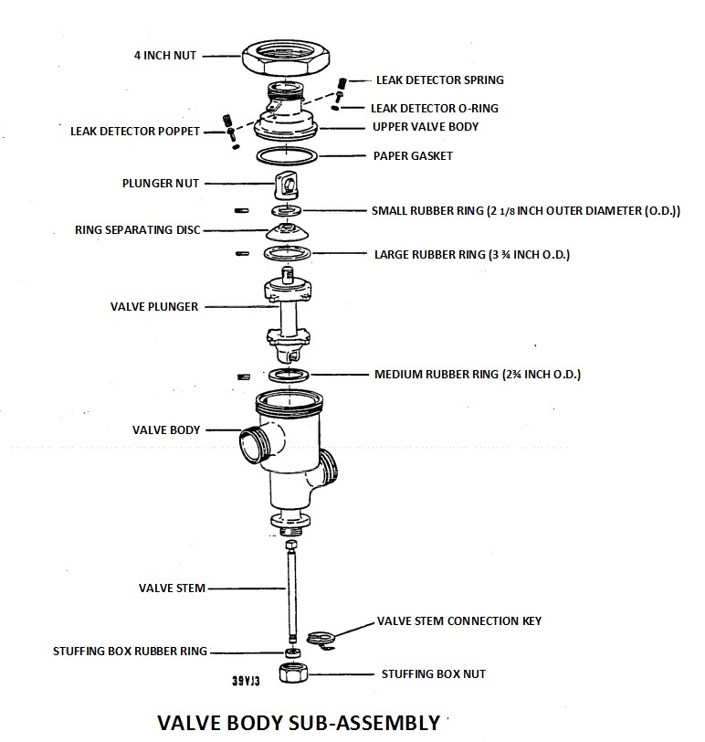
Description of image – Figure 1: Valve body sub-assembly
This diagram shows the parts of the valve body sub-assembly. It consists of:
- 4 inch nut
- Leak detector spring
- Leak detector O-ring
- Leak detector poppet
- Upper valve body
- Paper gasket
- Plunger nut
- Small rubber ring (2 ⅛ inch outer diameter (O.D.))
- Ring separating disc
- Large rubber ring (3 ¾ inch O.D.)
- Valve plunger
- Medium rubber ring (2¾ inch O.D.)
- Valve body
- Valve stem
- Valve stem connection key
- Stuffing box rubber ring
- Stuffing box nut
Reference: milk pasteurization controls and tests (red cow book), 8th edition, 2003
Test 12: Device assembly, single stem device
Application:
- All single stem FDDs used with HTST pasteurizers.
Frequency:
- Upon installation and at least once every 6 months thereafter.
- Whenever the microswitch is re-set or replaced.
Criteria:
- The FCD and all other flow promoting devices located between the constant level tank and the vacuum breaker stop or are isolated from the system when the FDD is improperly assembled.
Apparatus:
- Sanitary fitting wrench.
Method:
- Observe function of FCD when FDD is improperly assembled.
Procedure:
- With the system in operation with cold water and the FDD in diverted position unscrew by one-half turn, the 13H hex nut which holds the top of the valve to the valve body. This should de-energize the FCD and all other flow promoters. This test should be run with no piping connected to the forward flow port of the FDD since there can be sufficient force from the piping to keep the forward flow port tightly clamped even though the hex nut is loosened.
- With the system in operation with cold water and FDD in diverted position, remove the connecting key located at the base of the valve stem. The FCD and all other flow promoters should be de-energized.
- Record results.
Corrective action:
- If FCD fails to respond as indicated, immediately check the device assembly and wiring to locate and correct the cause.
- If after adjustment and/or repair the FDD fails this test, do not operate the pasteurization system until the cause of this failure has been corrected.
Test 13: Device assembly, dual stem device
Application:
- All dual stem FDDs used with HTST and HHST pasteurizers.
Frequency:
- Upon installation and at least once every 6 months thereafter
- Whenever the microswitch is re-set or replaced.
Criteria:
- The FCD and all other flow promoters stops or by-passed when the FDD is improperly assembled.
Apparatus:
- Tools to dismantle FDD.
Method:
- Observe function of FCD and all other flow promoters when FDD is improperly assembled.
Procedure A:
- While the pasteurizer is not operating, with the FDD in diverted flow, remove one actuator clamp.
- Move the FDD to the forward flow position using the "inspect" position of the selector switch and disconnect stem from actuator.
- Move the FDD to the diverted flow position using the "process" position of the selector switch and turn on the FCD. The FCD and all other flow promoters should not run or bypassed.
- Reassemble the FDD by moving it to the forward flow position and reconnecting the stem to the actuator.
- Move the FDD to the diverted flow position and replace the actuator clamp.
- Repeat the procedure for the other actuator.
- Record results.
Procedure B:
- With the FDD in the diverted flow position, move the microswitch away from the contact groove in the valve stem. Observe that the FCD and all other flow promoting devices are stopped or by-passed.
- Record results.
Procedure C:
- With the pasteurizer system in forward flow, insert a nut into the diversion valve quick exhaust port.
- Reduce the processing temperature below the cut-out temperature.
- Observe that the diversion valve does not immediately move to the fully diverted position, that all flow promoters stop and separator is by-passed.
- Repeat the test for leak detect valve.
- Record the results.
Procedure D:
For systems with a magnetic flow meter system used as a FCD:
- With the pasteurizer system in forward flow, insert a nut into the diversion valve quick exhaust port.
- Activate the high flow alarm.
- Observe that the diversion valve does not immediately move to the fully diverted position, that all flow promoters stop and separator is by-passed.
- Activate the low flow alarm or loss of signal alarm.
- Observe that the diversion valve does not immediately move to the fully diverted position, that all flow promoters stop and separator is by-passed.
- Repeat the test for leak detect valve.
- Record the results.
Corrective action:
- If FCD fails to respond as indicated, immediately check the device assembly and wiring to locate and correct the cause.
Figure 2: Valve exploded view
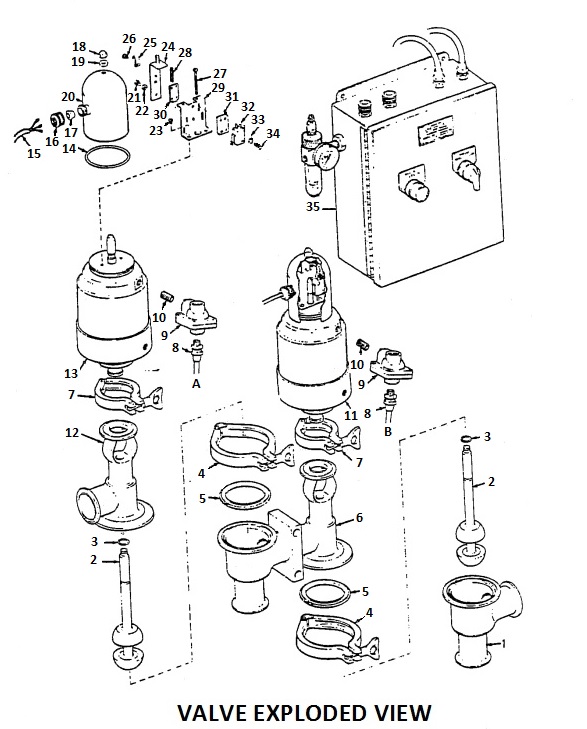
Description of image – Figure 2: Valve exploded view
This schematic is a dual stem diversion device, exploded view. It shows the different parts of a dual stem FDD, broken apart into the lower body, upper body, microswitch along with the control panel. The components include:
- Lower body - divert valve
- Valve plug assembly
- "O" ring - valve plug stem
- Clamp - body
- Gasket - body
- Body assembly - valve
- Clamp - actuator
- Connector - hose
- Quick exhaust valve
- Nipple - pipe
- Actuator assembly (complete)
- Upper body valve
- Actuator assembly
- "O" ring - base plate to housing
- Cable assembly
- Nut - cable grommet
- Grommet - cable
- Acorn nut
- Washer
- Housing - microswitch
- Screw - cover bracket
- Lockwasher - cover bracket
- Screw - microswitch bracket
- Bracket cover
- Loop clamp
- Screw - loop clamp
- Screw - microswitch adjusting
- Spring
- Bracket - microswitch
- Bracket - microswitch adjusting
- Block - microswitch mounting
- Microswitch
- Washer
- Screw - microswitch
- Control panel (complete)
Reference: Milk pasteurization controls and tests (Red Cow Book), 8th Edition, 2003
Test 14: Manual diversion
Application:
- HTST system with a booster pump.
Frequency:
- Upon installation and at least once every 6 months thereafter.
Criteria:
- When FDD is manually diverted, booster pump stops, frequency pen records a diverted flow position, green light goes out, red light comes on and pressure differential is maintained.
Apparatus:
- None.
Method:
- Observe the response of the system to manual diversion.
Procedure:
- With HTST system in operation and the FDD in the forward flow position, press the manual diversion button. Observe that the flow diversion valve assumes the divert position, and the booster pump stops. The frequency pen should record a diverted flow position, and the green light goes out while the red light comes on. The pressure differential between raw and pasteurized milk in the regenerator should be maintained.
- Activate the manual button while operating the HTST system at its maximum operating pressure. Confirm that the spring tension of the FDD is capable of diverting the system at maximum operating pressure.
- Operate the HTST system in forward flow and activate the manual divert button until the raw side pressure reaches 0 psi. Release the manual divert button and observe that the pressure differential between raw and pasteurized milk in the regenerator is maintained.
- Record the results.
Corrective action:
- If the above described actions do not occur when procedures 1, 2 and 3 are performed, or the necessary pressure differential between raw and pasteurized milk is not maintained, immediately review the assembly and wiring of the HTST system and correct the indicated deficiencies or make proper adjustments.
- If after adjustment and/ or repair the FDD fails this test, do not operate the pasteurization system until the cause of this failure has been corrected.
Test 15: Response time
Application:
- All FDDs used with HTST pasteurizer and HHST systems which use a dual stem valve assembly.
Frequency:
- Upon installation and at least once every 6 months thereafter.
Criteria:
- The FDD moves from the fully forward to the fully diverted position in no more than one second.
Apparatus:
- Stopwatch.
- Water, oil or other suitable media bath.
Method:
- Determine the elapsed time between the instant of the activation of the control mechanism at cut-out temperature on declining temperature and the instant the FDD takes the fully diverted flow position.
Procedure:
- Place the temperature sensing probe of the safety thermal limit recorder into the media bath.
- With media bath at a temperature above cut-out temperature, allow the media to cool gradually. At the moment the cut-out mechanism is activated, start the watch and the moment the FDD takes the fully diverted position, stop the watch. On a dual stem device, both valves should move simultaneously.
- Record results. Do not allow the response time interval to exceed one second.
Corrective action:
- If the response time exceeds 1 second, take immediate corrective action.
- If after adjustment and/or repair the FDD fails this test, do not operate the pasteurization system until the cause of this failure has been corrected.
Test 16: Valve flush time delay
Application:
- All dual stem FDDs in which product may be pocketed between the two valve seats while the valve is in diverted flow position (applicable to HTST only).
Frequency:
- Upon installation and at least once every 6 months thereafter.
- Whenever the seal on the time delay relay is broken.
Criteria:
- There is a flush of the transitional cavity between the two valves of at least 1 second. If a restrictor is installed in the divert line, the delay is no longer than 3 seconds.
- The maximum three seconds of delay is not applicable when the timing system is magnetic flow meter based.
Apparatus:
- Stopwatch.
Method:
- When the FDD moves from the diverted flow position to the forward flow position, observe that the cavity located between the two valve bodies receives an adequate flush to remove stale product, and that this flush does not compromise the required hold time.
Procedure:
- Operate the pasteurizer in diverted flow position.
- Raise the temperature to a point above the cut-in temperature.
- At the instant the divert (first) valve begins to move into its "forward flow" position, start the stopwatch.
- At the instant the leak detect valve begins to move, stop the stopwatch.
- Record the result and adjust the time delay relay if necessary (and seal the time delay relay or its enclosure).
Corrective action:
- Should the valve flush time be less than one second and greater than three seconds in the restrictor installed divert line, immediate corrective action must be taken.
- If after adjustment and/or repair the FDD fails this test, do not operate the pasteurization system until the cause of this failure has been corrected.
Test 17: Time delay interlock with FCD
Application:
- To dual stem FDDs with a manual forward flow switch (inspect position on the mode switch) (applicable to HTST and HHST pasteurizers).
Frequency:
- Upon installation and at least once every 6 months thereafter.
Criteria:
- To verify that the system cannot enter a manually induced forward flow position while the FCD is running or any flow promoting device located between the constant level tank and the vacuum breaker is active.
Apparatus:
- None.
Method:
- Determine that the FDD does not assume a manually induced forward flow position while FCD is running or any flow promoting device located between the constant level tank and the vacuum breaker is active.
Procedure:
- With the system running in forward flow, move the control switch to the "inspect" position and observe that the following events automatically occur in sequence.
- The FDD immediately moves to the diverted flow position and the FCD is turned off.
- The FDD remains in the diverted flow position while the FCD is running down.
- All flow promoting devices are either de-energized or by-passed.
- After the FCD stops running, the FDD assumes the forward flow position. All flow promoting devices remain de-energized or by-passed.
- Record results and seal the timer or enclosure.
Corrective action:
- If the above sequence of events does not occur, either adjust the timer or change the wiring.
- If after adjustment and/or repair the FDD fails this test, do not operate the pasteurization system until the cause of this failure has been corrected
Test 18: Clean-in-place (CIP) time delay relay
Application:
- All HTST and HHST pasteurizer systems in which it is desired to run the FCD and/or other flow promoting device during the CIP cycle.
Frequency:
- Upon installation and at least once every 6 months thereafter.
- Whenever the seal on the time delay relay is broken.
Criteria:
- When the mode switch on the FDD is moved from "process product" to "CIP", the FDD moves immediately to the diverted position and remains in the diverted position for at least 10 minutes before starting its normal cycling in the CIP mode.
- In HTST systems the booster pump turns off and does not run during the 10 minute time delay.
Apparatus:
- Stopwatch.
Method:
- Determine that the set point on the CIP time delay relay is equal to or greater than 10 minutes by observing the time when the FDD moves to the forward-flow position or is again capable of moving to the forward-flow position.
Procedure:
- Operate pasteurizer in forward flow with the mode switch on the FDD in the "process product" position, at a flow rate below the value at which holding time was measured, using water above pasteurization temperature.
- Move the mode switch on the FDD to the "CIP" position. The FDD should move immediately to the diverted position and the booster pump should stop running.
- Start the stopwatch when the FDD moves to the diverted position.
- Stop the stopwatch when the FDD moves to the forward flow position for its initial cycle in the CIP mode or when the booster pump starts.
- Record results. The time delay must be at least 10 minutes.
Corrective action:
- If the FDD does not remain in the diverted position for at least 10 minutes after the mode switch is moved from "process product" to "CIP", increase the set point on the time delay relay and repeat this test procedure.
- If the booster pump runs at any time during the 10 minute delay, repair the booster pump wiring. If after adjustment and/or repair the FDD fails this test, do not operate the pasteurization system until the cause of this failure has been corrected.
Pressure differential
Test 19: Pinholes check - dye recirculation procedure
Note
Other validated tests (for example, spraying dye, Freon method, helium test, pressure method etc.) can also be used.
Application:
- All heat transfer plates of HTST, APPS and HHST pasteurizers and all other transfer plate systems in the establishment.
Frequency:
- At least once a year and more often if the integrity of the transfer plates is in question.
Criteria:
- To check for pinholes in the heat transfer plates.
Apparatus:
- Connections and fittings to circulate the back side of all non-product surfaces of plates (i.e. hot water, chill water and glycol sections) and raw side of regenerator in one complete circuit.
Method:
- Circulate potassium permanganate solution on both sides of heat exchanger plates.
- A pinhole in plate will show dye on 2 plates (the one with leak and the one opposite).
Procedure:
- Clean up pasteurizer system in a normal manner.
- Make necessary connections to circulate the back side of all non-product surfaces of plates (hot water, chill water and glycol sections). This should be accomplished with one circulation to clean all sections at one time.
- Fill constant level tank with water. Begin pumping water to flush back side of plates until water runs clear.
- Direct flow to constant level tank to start circulation.
- Clean both sides of the plates properly with a recommended procedure. Flush thoroughly with warm or hot water.
- Open up the heat exchanger. Inspect each plate for proper cleaning. Plates which are not cleaned will need hand scrubbing to get clean.
- If plates are clean, leave plates spread apart and spaced. All plates must be dry and clean before proceeding to the next step.
- Close up the heat exchanger. Hook up to circulate non-product side of plates as well as raw side of the regenerator in one complete circuit.
- Add water to constant level tank. Do not turn on pump.
- Mix in potassium permanganate dye in constant level tank using a stirring rod (approximately 3.5 kg per 1000 litres water).
- Begin pumping potassium permanganate solution and adding water if necessary to keep constant level tank from running dry. Stop adding water when level in constant level tank is satisfied.
- Add approximately 4.5 litres liquid caustic solution (or 2.5 kg caustic powder mixed in 5 litres water) to constant level tank.
- Heat to 82ºC. Turn off the steam supply once this temperature is reached.
- Circulate for 30 minutes. Do not be concerned with drop in temperature during remainder circulation period.
- Pump dye solution to floor drain until constant level tank runs dry. Do not add water.
- Shut off pump when reservoir runs dry.
- Disconnect connections. Allow the heat exchanger to drain. Rinse off the floor and outside of the heat exchanger while the heat exchanger is draining.
- Open up the heat exchanger and allow to drain completely. Rinse any dye solution traces from exterior of equipment, floor etc. Inspect each pair of product plates.
- A hole in the heat exchanger will show potassium permanganate dye on 2 plates (i.e. the one with leak and one opposite).
- Manually dye check both plates to determine which is leaking.
- After all plates have been inspected, reconnect and circulate Oxalic acid at the rate of 100 mL per 45 litres of water through same circuit as the potassium permanganate dye solution to neutralize the dye. Heat to 60ºC. Use Oxalic acid solution from the constant level tank to clean dye from all areas where splattering has occurred.
- Connect the heat exchanger up for normal product clean-up and re-clean with normal procedure.
- Record results.
Corrective action:
- Replace all heat transfer plates with pinholes.
Test 20: Pressure differential controller
Application:
- To those pressure differential controllers having pneumatically driven pointers, used to control the operation of booster pumps on HTST pasteurizers.
- In the case of product-to-heat transfer medium-to-product type regeneration, the heat transfer medium pump is considered as the booster pump.
Frequency:
- Upon installation and at least once every 6 months thereafter.
Criteria:
- The booster pump does not operate unless the product pressure in the pasteurized side of regenerator is at least 2 psi (14 kPa) greater than the product pressure in the raw side of the regenerator.
Apparatus:
- Optional: pneumatic testing device as shown in Figure 3.
Method:
- The pressure differential controller is checked and adjusted to prevent operation of the booster pump, unless the product pressure in the pasteurized side of the regenerator is at least 2 psi (14 kPa) greater than pressure in the raw side of the regenerator.
Procedure A:
- Loosen the connections at both pressure sensors and wait for any liquid to drain through the loose connections. Observe that both pointers are within ±0.5 psi of zero psi (0 kPa).
- Remove both sensors from the process and mount them in a tee, either at the discharge of the booster pump, or connected to the pneumatic testing device. Note the difference between the sensor readings. The change in elevations of the sensors may have caused some change in the zero readings.
- Turn on the booster pump switch and depress the test push button to operate the booster pump. Observe that the difference between the sensor readings is within 1 psi (7 kPa) of that observed before pressure was applied.
- Turn off the booster pump switch and return the pressure sensors to their normal process locations.
- Manually move and hold the white pointer (raw side of the regenerator) at the normal operating pressure of the booster pump.
- Press the test button while manually moving the orange pointer (pasteurized side of the regenerator) upscale until the pilot light turns on, then slowly move the orange pointer downscale until pilot light turns off.
- Observe that the pilot light does not turn on until the orange pointer is at least 2 psi (14 kPa) higher than white pointer, and the pilot light turns off when the orange pointer is no less than 2 psi (14 kPa) higher than the white pointer.
- If necessary, adjust the differential setting.
Note
The test may also be completed using a pneumatic testing device capable of producing differential pressures on the probes. This device should be capable of performing and be operated in a manner so as to duplicate the conditions described above.
Procedure B:
Note
The application also includes electronically operated pressure differential controllers.
- Follow steps 1 and 2 in Procedure A.
- Operate the system in forward flow.
- Reduce the pressure in the pasteurized product regenerator section by slowly opening the back pressure control valve, or increase the raw product pressure by slowly opening the flow control valve (if present) located between the booster pump and the raw product pressure sensor.
- Observe that the booster pump stops and the pressure differential controller pilot light goes out when the pasteurized product pressure is no less than 2 psi (14 kPa) higher than raw product pressure. The booster pump cut out point is indicated by sudden decrease in raw product pressure.
Note
The 2 psi (14 kPa) differential represents the sum of the 1 psi (7 kPa) differential required between raw and pasteurized product in the regenerator, plus the 1 psi (7 kPa) imprecision permitted between the two pressure sensors. Should the pasteurized milk regenerator outlet be at the bottom of the pasteurizer, the pressure differential must be increased by the head pressure within the pasteurizer.
Note
This test may also be completed by using a pneumatic testing device consisting of two independently adjusted pressure connections to simulate raw and pasteurized product pressure conditions.
Figure 3: Pneumatic testing device

Description of image – Figure 3: Pneumatic testing device
This schematic describes the basic design and components of a pneumatic testing device. Components are:
- Air gauge or sensing element
- Reducer
- Tee
- Pressure switch or sensing element
- Reducer
- Cap of correct type, drilled and tapped to accept ¼ inch pipe
- 0-100 psig gauge ½% accuracy
- Needle valve
- Vent
- Pressure regulator
- Air supply min. - 70 psig (pounds per square inch gauge)
Test 20.1: Inter-wiring of the pressure differential recorder controller with the FDD
Application:
- A: All differential pressure controllers used to control the operation of FDDs on HHST systems when no vacuum breaker is located downstream from the holding tube, and
- B: All differential pressure controllers used to control the operation of FDDs, product divert systems, product divert valve(s) or other acceptable control systems used in APPS.
Frequency:
- Upon installation and at least once every 6 months thereafter.
Criteria:
- The differential controller is inter-wired with the FDD so that divert occurs when the sterilized product pressure in the regenerator drops to less than 2 psi (14 kPa) from that on the raw side of the regenerator and remains in diverted flow until proper pressures are re-established.
- In the case of product-to-heat transfer medium-to-product regenerators, where the protection is on the pasteurized or aseptic side, the "heat transfer medium" side of the regenerator is considered to be the "raw product" side for purposes of this test.
Apparatus:
- Sanitary pressure gauge.
- Pneumatic testing device as shown in Figure 3.
Method:
- The differential pressure switch is checked and adjusted to prevent forward flow, unless the product pressure in the pasteurized side of the regenerator is at least 2 psi (14kPa) greater than the pressure in the raw product side of the regenerator.
- In the case of product to water to product regenerators protected on the pasteurized or aseptic side, the water side of the regenerator shall be considered to be the "raw product" for purposes of this test.
Procedure:
- Wire the test lamp in series with the signal from the pressure differential switch to the FDD.
- Calibrate the pressure switch and probes (using Test 20, procedure A).
- Adjust the pressure on the pressure switch sensors to their normal operating pressures (with the pasteurized, or aseptic pressure at least 14 kPa (2 psi) higher than the raw product pressure.
- The test lamp should be lit. If not, increase the pasteurized, or aseptic pressure (or lower the raw product pressure) until the test light is lit.
- Gradually lower the pasteurized, or aseptic side (or raise the raw product pressure) until the test light turns off.
- The test light should turn off when the pasteurized or aseptic pressure is at least 14 kPa (2 psi) higher than the raw product pressure.
- Note the differential pressure at the point the light turns off.
- Gradually raise the pasteurized, or aseptic pressure (or lower the raw product pressure) until the test light turns on.
- The test light should not turn on until the pasteurized, or aseptic pressure is greater than 14 kPa (2 psi) higher than the raw product pressure. Note the differential pressure at the point the light turns off.
Note
This test may be completed using a pneumatic testing device capable of producing differential pressures on the probes. This device should be capable of being operated in a manner so as to duplicate the conditions described above.
- Seal the instrument and record the test results for the office record.
Corrective action:
- If the differential pressure controller fails to respond as indicated above, do an immediate check of the differential pressure to locate and correct the problem.
- If after adjustment and/or repair the differential pressure controller fails this test, do not operate the pasteurization system until the cause of this failure has been corrected.
Test 21: Pressure gauges - displays
Application:
- Pressure display of the pressure differential controller and all pressure gauges on the HTST pasteurizer and any other heat transfer plate systems to monitor pressure.
Frequency:
- Upon installation and at least once every 6 months thereafter, and whenever the gauges are adjusted or repaired.
Criteria:
- Required pressure gauges and displays are accurate.
Apparatus:
- Pneumatic testing device as shown in Figure 3 above or equivalent.
- Pressure gauge of known accuracy.
Method:
- Verify the accuracy of required pressure gauges and displays with an accurate gauge.
Procedure:
- Pressure gauge of known accuracy is connected to one outlet of test apparatus.
- Pressure gauge or display sensor being checked is connected to the second outlet of the sanitary tee.
- Air is bled into system through third outlet and comparative readings are made throughout the normal operating range for that gauge or display.
- Record results.
Corrective action:
- Return inaccurate gauges or displays to the factory for repair.
Test 22: Booster pumps - inter-wired with FDD
Application:
- All booster pumps used for HTST pasteurizer systems.
- In product-to-heat transfer medium-to-product type regeneration, the heat transfer medium pump is considered as the booster pump.
Frequency:
- Upon installation and at least once every 6 months thereafter, and after any change in the booster pump or switch circuits.
Criteria:
- Wire the booster pump so it cannot operate if the FDD is in the diverted position.
Apparatus:
- Pneumatic testing device as shown in Figure 3.
- Sanitary pressure gauge.
- Water, oil or other suitable media bath and agitator.
- Suitable means of heating the media bath.
Method:
- Determine if the booster pump stops by dropping the temperature and causing the FDD to divert.
Procedure:
- Connect pasteurization pressure sensor to the tee of the testing device with the other end of the tee capped.
- Turn on the air supply to provide an adequate pressure differential.
- Place the safety thermal limit recorder probe in the hot media bath, which is above the cut-in temperature.
- Cap the safety thermal limit recorder probe and pasteurized sensor port if the pasteurizer has water in it.
- Turn on the FCD. At this time, the booster pump should start to run.
- Remove the safety thermal limit recorder probe from the hot media bath.
- When the FDD moves to the diverted flow position, the booster pump must stop.
- Ensure that the pressure differential remains adequate and the FCD continues to operate following its momentary pause during the FDD transition.
- Record the test results.
Criteria:
- If the booster pump fails to stop when the FDD is in the diverted flow position, check the wiring and correct the cause.
- If after adjustment and/or repair the booster pump fails this test, do not operate the pasteurization system until the cause of this failure has been corrected.
Test 23: Booster pumps - inter-wired with pressure differential controller
Application:
- All booster pumps used for HTST pasteurizer systems.
- In product-to-heat transfer medium-to-product type regeneration, the heat transfer medium pump is considered as the booster pump.
Frequency:
- Upon installation and at least once every 6 months thereafter.
- After any change in the booster pump or switch circuits.
Criteria:
- Wire the booster pump so it cannot operate if the pasteurized product pressure in the regenerator does not exceed, by at least 2 psi (14 kPa), the product pressure in the raw side of the regenerator.
Apparatus:
- Pneumatic testing device as shown in Figure 3.
- Sanitary pressure gauge.
- Water, oil or other suitable media bath and agitator.
- Suitable means of heating the water bath.
Method:
- Determine if the booster pump stops when the pressure differential is not properly maintained in the regenerator.
Procedure:
- Connect pasteurization pressure sensor to the tee of the testing device with the other end of the tee capped.
- Turn on the air supply to provide an adequate pressure differential.
- Place the safety thermal limit recorder probe in the hot water bath, which is above the cut-in temperature.
- Cap the safety thermal limit recorder probe and pasteurized sensor port.
- Turn on the FCD. At this time, the booster pump should start to run.
- Decrease the air supply to the testing tee until the pressure is less than 2 psi (14 kPa) of the pressure on the raw milk pressure sensor. The booster pump should stop.
- Ensure that the FDD remains in the forward flow position and the FCD continues to operate.
- Record the test results.
Corrective action:
- If the booster pump fails to stop when the pressure differential is not maintained, determine and correct the cause.
- If after adjustment and/or repair the differential pressure controller fails this test, do not operate the pasteurization system until the cause of this failure has been corrected.
Test 24: Booster pumps - Inter-wired with FCD (timing pump, metering pump
Application:
- All booster pumps used for HTST
- In product-to-heat transfer medium-to-product type regeneration, the heat transfer medium pump is considered as the booster pump.
- All feed and heat transfer medium pumps used in HHST and aseptic processing systems.
Frequency:
- Upon installation and at least once every 6 months thereafter.
- After any change in the pumps or switch circuits.
Criteria:
- Wire the booster, heat transfer medium, and/or feed pumps so they cannot operate if the FCD is not in operation.
Apparatus:
- Pneumatic testing device as shown in Figure 3.
- Sanitary pressure gauge.
- Water, oil or other suitable media bath and agitator.
- Suitable means of heating the water bath.
Method:
- Determine if the booster, heat transfer medium and/or feed pump stops when the FCD is off.
Procedure:
- Connect pasteurization pressure sensor to the tee of the testing device with the other end of the tee capped.
- Turn on the air supply to provide an adequate pressure differential.
- Place the safety thermal limit recorder probe in the hot water bath, which is above the cut-in temperature.
- Cap the safety thermal limit recorder probe and pasteurized sensor port.
- Turn on the FCD. At this time, the booster/heat transfer medium/feed pump should start to run.
- Turn off the FCD. The booster, heat transfer medium and feed pump must stop.
- Ensure that the pressure differential remains adequate and the FDD remains in forward flow position.
- Record the test results.
Corrective action:
- If the booster, heat transfer medium and/or feed pump fails to stop when the FCD has been turned off, determine and correct the cause.
- If after adjustment and/or repair the booster pump fails this test, do not operate the pasteurization system until the cause of this failure has been corrected.
Meter based timing systems
Test 25: High flow alarm
Application:
- All HTST pasteurizers, HHST and aseptic processing systems using a meter based timing system to replace a positive displacement FCD.
Frequency:
- Upon installation and at least once every 6 months thereafter.
- Whenever seal on the flow alarm is broken.
Criteria:
- When flow rate equals or exceeds the value at which the holding time was measured, verify the FDD assumes the diverted position, even though the temperature of the milk in the holding tube is above pasteurization temperature.
Apparatus:
- None.
Method:
- Adjust the set point of the flow alarm so that the flow is diverted when the flow rate equals or exceeds the value at which holding time was measured or calculated.
Procedure:
- Operate the HTST, HHST pasteurizer or the aseptic processing equipment in forward flow, below the high flow alarm, using water above pasteurization temperature.
- Adjust set point on the alarm slowly downward until the frequency pen on the flow recorder indicates that an alarm condition has occurred.
- Observe that the FDD moved to the diverted position while water passing through the system remained above pasteurization temperature. Verify that the frequency pen on the flow recorder records the duration of the high flow condition.
- Record the set point of the flow alarm, the occurrence of flow diversion, and the temperature of water in the holding tube.
Corrective action:
- If the FDD does not move to the diverted position, when the frequency pen of the recorder indicates a diversion, modify or repair the control wiring.
- If after adjustment the pasteurization system fails this test, do not operate the pasteurization system until the cause of this failure has been corrected.
Test 26: Loss of signal alarm
Application:
- All HTST pasteurizers, HHST and aseptic processing systems using a magnetic flow meter system to replace a positive displacement FCD.
Frequency:
- Upon installation and at least once every 6 months thereafter.
- Whenever seal on the flow alarm is broken.
- Whenever alteration is made affecting the holding time, the velocity of the flow or the capacity of the holding tube.
- Whenever a check of the system indicates a speed-up.
Criteria:
- Verify forward flow occurs only when flow rates are below the flow alarm set point and above (5% of the maximum) the loss of signal alarm set point.
Apparatus:
- None.
Method:
- Observe the actions of the frequency pen on the flow recorder and the position of the FDD.
Procedure:
- Operate the HTST, HHST pasteurizer or aseptic processing system with the FDD in the forward flow position, at a flow rate below the flow alarm set point and above (5% of the maximum) the loss of signal alarm set point, using water.
- Disrupt power to the magnetic flow meter or decrease the flow through the flow meter below the low flow alarm set point.
- Observe that the frequency pen of the flow recorder records an alarm condition for the duration of the loss of signal or low flow condition, and that the FDD moves to the diverted flow position for the duration of this condition.
- Record the results.
Corrective action:
- If the valve does not divert or the pens do not move, adjust the low flow alarm or modify or repair the control wiring.
- If after adjustment the pasteurization system fails this test, do not operate the pasteurization system until the cause of this failure has been corrected.
Test 27: Flow cut-in and cut-out
Application:
- All HTST pasteurizers, HHST and aseptic processing systems using a magnetic flow meter system to replace a positive displacement FCD.
Frequency:
- Upon installation and at least once every 6 months thereafter.
- Whenever seal on the flow alarm is broken.
- Whenever any alteration is made affecting the holding time, the velocity of the flow or the capacity of the holding tube.
- Whenever a check of the capacity indicates a speed-up.
Criteria:
- Verify forward flow occurs only when flow rates are below the flow alarm set point and above the loss of signal alarm set point.
Apparatus:
- None.
Method:
- Observe the recorder readings along with the action of the frequency pen on the flow recorder.
Procedure:
- Operate pasteurizer in forward flow, at a flow rate below the flow alarm set point and above loss of signal alarm set point, using water above pasteurization temperature.
- Using the flow controller, increase flow rate slowly until the frequency pen on the flow recorder indicates an alarm condition (flow cut-out point). The FDD will also assume the diverted position.
- Observe the reading of flow rate from the recorder, the instant flow cut-out occurs, as indicated by the frequency pen of the flow recorder.
- With the pasteurizer operating on water above the pasteurization temperature, with the FDD diverted because of excessive flow rate, slowly decrease flow rate until the frequency pen on the flow recorder indicates the start of a forward flow movement (flow cut-in point). Because of the time delay relay described in Test 28, the FDD will not move immediately to the forward flow position.
- Observe the reading from the recorder, the instant flow cut-in occurs, as indicated by the frequency pen of the flow recorder.
- Record results.
Corrective action:
- If the cut-in or cut-out point occurs at a flow rate equal to or greater than the value at which holding time was measured, adjust the flow alarm to a lower set point and repeat the test.
- If after adjustment the pasteurization system fails this test, do not operate the pasteurization system until the cause of this failure has been corrected.
Test 28: Time delay relay (flow recorder)
Application:
- All HTST pasteurizers using magnetic flow meter system to replace a positive displacement FCD.
Frequency:
- Upon installation and at least once every 6 months thereafter.
- Whenever seal on the flow alarm is broken.
- Whenever any alteration is made affecting the holding time, the velocity of the flow or the capacity of the holding tube.
- Whenever a check of the capacity indicates a speed-up.
Criteria:
- Following a flow cut-out, as described in the test for flow cut-in and cut-out (test 27), verify forward flow does not occur until all the product in the holding tube has been held at or above pasteurization temperature for at least the minimum holding time of the product with the longest required holding time.
- For example, 15 seconds or 25 seconds depending on the products.
Apparatus:
- Stopwatch.
Method:
- Set the time delay equal to or greater than the minimum holding time.
Procedure:
- Operate pasteurizer in forward flow, at a flow rate below the flow alarm set point and above the loss of signal alarm set point, using water above pasteurization temperature.
- Using the flow controller, increase flow rate slowly until the frequency pen on the flow recorder indicates an alarm condition, and the FDD moves to the diverted position. There should be no time delay between the movements of the frequency pen and the FDD.
- With the pasteurizer operating on water above the pasteurization temperature, with the FDD diverted because of excessive flow rate, slowly decrease flow rate.
- Start the stopwatch the instant the frequency pen on the flow recorder indicates the end of the alarm condition.
- Stop the stopwatch the instant the FDD starts to move to the forward flow position.
- Record results.
Corrective action:
- If the time delay is less than the minimum holding time, increase the time setting on the time delay and repeat this test procedure.
- If after adjustment the pasteurization system fails this test, do not operate the pasteurization system until the cause of this failure has been corrected.
Test 29: Thermal limit controller for control-sequence logic
- Test thermal limit controllers used with HHST and aseptic processing systems that have the flow-diversion device located downstream from the regenerator and/or cooler using one of the following tests at the frequency specified.
29.1 HHST pasteurization and aseptic processing-indirect heating
Application:
- All HHST and aseptic processing systems pasteurizers using indirect heating.
- When testing aseptic processing systems, the "product divert system" or "product divert valve" or "acceptable control system" may be substituted for the "flow-diversion device" when it is referenced in this test.
Frequency:
- Upon installation, and every 6 months thereafter.
- Whenever a seal has been broken.
Criteria:
- Verify the pasteurizer or aseptic processing equipment does not operate in forward flow until the product contact surfaces downstream from the holding tube have been held at or above the required pasteurization temperature for the required time or, in the case of aseptic processing equipment, sterilized.
- On start-up, expose contact surfaces to fluid at pasteurization, or in the case of aseptic processing equipment, sterilization temperature, for at least pasteurization or sterilization time.
- If the product temperature falls below the pasteurization or sterilization standard in the holding tube, ensure forward flow is not re-achieved until the product contact surfaces downstream from the holding tube have been re-held at or above the required pasteurization temperature for the required time, or in the case of aseptic processing equipment, re-sterilized.
Apparatus:
- Constant temperature water, oil or other suitable media bath.
- Test lamp from the pneumatic testing device as shown in Figure 3.
Method:
- Determine the control-sequence logic of the thermal limit controller by monitoring the electric signal from the thermal limit controller during a series of immersions and removals of the two sensing elements from a media bath heated above the cut-in temperature.
Procedures:
- Heat the media bath to a constant temperature, a few degrees above the cut-in temperature on the safety thermal limit controller.
- Wire the test lamp in series with the signal from the thermal limit controller to the flow-diversion device. If you have time delays built into your control logic in excess of that required for food safety, bypass these timers or account for their effect in delaying forward flow.
- Immerse the holding tube sensing element in the bath, which is above the cut-in temperature. The test lamp should remain unlit, indicating diverted flow. Leave the sensing element in the bath.
- Immerse the 2nd or more as required sensing element in the bath. The test lamp should light up, i.e. forward flow after a minimum time delay of 1 second for continuous flow pasteurization systems. For aseptic processing systems, no delay is required if the filed process includes a documented sterilization period.
- Remove the 2nd or more as required elements from the bath. The test lamp should remain lit, i.e. forward flow.
- Remove the holding tube sensing element from the bath. The test lamp should go out immediately (i.e. diverted flow, sterilization timer not timing).
- Re-immerse the sensing element of the holding tube in the bath. The test lamp should remain unlit, indicating diverted flow. Record results.
- With all elements in the bath, observe the sterilization timer. Start the watch when the test lamps light (cut-in temperature) turns on.
- Record the time. Compare the results to the scheduled process to verify that the time meets that specified by the process authority.
- Stop the watch when the sterilization timer has elapsed.
- Record this time.
Corrective action:
- If the control-sequence logic of the thermal limit controller does not follow the pattern set out in the procedures section, reconfigure the instrument to conform to this logic.
- If after reconfiguration, the pasteurization system fails this test, do not operate the pasteurization system until the cause of this failure has been corrected.
29.2 HHST pasteurization and aseptic processing - direct heating
Application:
- All HHST pasteurizers and aseptic processing systems using direct contact heating.
- When testing aseptic processing systems, the "product divert system" or "product divert valve" or "acceptable control system" may be substituted for the "flow-diversion device" when it is referenced in this test.
Frequency:
- Upon installation and every 6 months thereafter.
- Whenever a seal has been broken.
Criteria:
- Verify the pasteurizer or aseptic processing equipment does not operate in forward flow until the product contact surfaces downstream from the holding tube have been held at or above the required pasteurization temperature for the required time or, in the case of aseptic processing equipment, sterilized.
- On start-up, expose contact surfaces to fluid at pasteurization or, in the case of aseptic processing equipment, sterilization temperature, for at least pasteurization or sterilization time.
- If the product temperature falls below the pasteurization or sterilization standard in the holding tube, ensure forward flow is not re-achieved until the product contact surfaces downstream from the holding tube have been re-held at or above the required pasteurization temperature for the required time, or in the case of aseptic processing equipment, re-sterilized.
Apparatus:
- Constant temperature water, oil or other suitable media bath.
- Test lamp from the pneumatic testing device as shown in Figure 3.
Method:
- Determine the control-sequence logic of the thermal limit controller by monitoring the electric signal from the thermal limit controller during a series of immersions and removals of the three sensing elements, located at the FDD, vacuum chamber and in the holding tube, from a media bath heated above the cut-in temperature.
Procedures:
- Heat media bath to a constant temperature, a few degrees above the cut-in temperature on the thermal limit controller.
- Wire the test lamp in series with the signal from the thermal limit controller to the flow-diversion device. If time delays are built into the control logic in excess of that required for food safety reasons, bypass these timers or account for their effect in delaying forward flow. The pressure switches which must be closed to achieve forward flow must also be bypassed before performing this test.
- Immerse the sensing element from the flow-diversion device in the media bath, which is above the cut-in temperature. The test lamp should remain unlit, indicating diverted flow. Remove this sensing element from the bath.
- Immerse the sensing element from the vacuum chamber in the bath. The test lamp should remain unlit, indicating diverted flow. Remove the sensing element from the bath.
- Immerse the two sensing elements, from the vacuum chamber and flow-diversion device, in the bath. The test lamp should remain unlit, indicating diverted flow. Leave these two sensing elements in the bath.
- Immerse the sensing element from the holding tube in the bath. The test lamp should light up, indicating forward flow, after a minimum time delay of 1 second for continuous flow pasteurization systems. For aseptic processing systems, no delay is required if the filed process includes a documented sterilization period.
- Remove the sensing element from the flow-diversion device from the bath. The test lamp should remain lit, indicating forward flow.
- Remove the sensing element from the vacuum chamber from the bath. The test lamp should remain lit, indicating forward flow.
- Remove the remaining sensing element from the holding tube from the bath. The test lamp should go out immediately, indicating diverted flow.
- Re-immerse the sensing element from the holding tube in the bath. The test lamp should remain unlit, indicating diverted flow.
- Record results.
- Re-seal controls as necessary.
Corrective action:
- If the control-sequence logic of the thermal limit controller does not follow the pattern set out in the procedures section, reconfigure the instrument to conform to this logic.
- If after reconfiguration the pasteurization system fails this test, do not operate the pasteurization until the cause of this failure has been corrected.
Test 30: Setting of control switches for product pressure in the holding tube
Application:
- All HHST pasteurizers and aseptic processing systems which are capable of operating with product in forward flow mode, with less than 518 kPa (75 PSIG) pressure in the holding tube.
- When testing aseptic processing systems, the "product divert system" or "product divert valve" or "acceptable control system" may be substituted for the "flow-diversion device" when it is referenced in this test.
Frequency:
- Upon installation and at least once every 6 months thereafter.
- Whenever the pressure switch seal is broken.
- Whenever the operating temperature is changed.
Criteria:
- Verify the pasteurizer or aseptic processor does not operate in forward flow unless the product pressure in the holding tube is at least 69 kPa (10 psi) above the boiling pressure of the product.
Apparatus:
- Sanitary pressure gauge.
- Test lamp from the pneumatic testing device as shown in Figure 3.
Method:
- Check and adjust the pressure switch to prevent forward flow unless the product pressure in the holding tube is at least 69 kPa (10 psi) above the boiling pressure of the product.
Procedure:
- From figure 4, determine the pressure switch setting necessary for the operating temperature (not the diversion temperature) being used in the process.
- Install the sanitary pressure gauge of known accuracy and the pressure switch sensing element on the pneumatic testing device.
- Remove the seal and cover to expose the adjustment mechanism on the pressure switch.
- Place the test lamp in series with the pressure switch contacts or use some other method to monitor the cut-in signal.
- Apply air pressure to the sensing element and determine the pressure gauge reading at the cut-in point of the switch, which will light the test lamp. If the switch is short circuited, the lamp will be lit before air pressure is applied.
- Determine that the cut-in pressure on the switch is equivalent to or greater than the required pressure from the figure below.
- Record results.
- Where adjustment is necessary, refer to manufacturer's instruction.
- After adjustment, repeat the above procedure.
- When the results are satisfactory, seal the pressure switch setting.
- For each operating temperature on HHST pasteurizers using direct contact heating, the product pressure switch setting is determined from the figure below.
Corrective action:
- If forward-flow is achieved with less than 69 kPa (10 psi) above the boiling point of the milk and/or milk product in the holding tube, adjust the pressure setting and retest.
- If after adjustment the pasteurization system fails this test, do not operate the pasteurization system until the cause of this failure has been corrected.
Note
The pressure setting is adjusted upward by the difference between local normal atmospheric pressure and at sea level.
Figure 4: Pressure switch settings
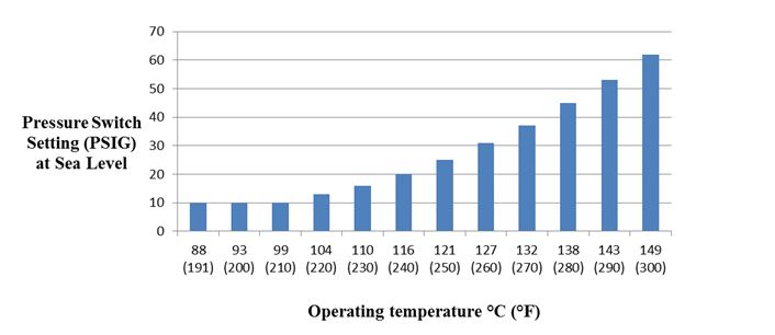
Description of image – Figure 4: Pressure switch settings
This chart shows the operating temperatures of different pressure switch settings at sea level.
- At temperatures of 88°C (191°F) to 99°C (210°F) the pressure switch setting is 10 pounds per square inch gauge (psig) at sea level.
- At 104° C (220°F) the pressure switch setting is 13 PSIG at sea level
- At 110°C (230°F) the pressure switch setting is 16 PSIG at sea level.
- At 116°C (240°F) the pressure switch setting is 20 PSIG at sea level.
- At 121°C (250°F) the pressure switch setting is 25 PSIG at sea level.
- At 127°C (260°F) the pressure switch setting is 31 PSIG at sea level
- At 132°C (270°F) the pressure switch setting is 37 PSIG at sea level.
- At 138°C (280°F) the pressure switch setting is 45 PSIG at sea level.
- At 143°C (290°F) the pressure switch setting is 53 PSIG at sea level.
- At 149°C (300°F) the pressure switch setting is 62 PSIG at sea level.
Test 31: Setting of control switches for differential pressure across the injector
This test is to determine that there is at least a 10 psi pressure loss of product at exit end of the steam injector. This assures complete condensation of the steam within the injector.
Application:
- All HHST pasteurizers and aseptic processing systems using direct steam injection heating.
- When testing aseptic processing systems, the "product divert system" or "product divert valve" or "acceptable control system" may be substituted for the "flow-diversion device" when it is referenced in this test.
Frequency:
- Upon installation and at least once every 6 months thereafter.
- Whenever the differential pressure controller seal is broken.
Criteria:
- Verify the pasteurizer or aseptic processor does not operate in forward flow unless the product pressure drop across the steam injector is at least 69 kPa (10 psi).
Apparatus:
- Sanitary pressure gauge.
- Test lamp from the pneumatic testing device as shown in Figure 3.
Method:
- Check the differential pressure switch and adjust it to prevent forward flow, unless the differential pressure across the steam injector is at least 69 kPa (10 psi).
Procedure A: Calibration of the steam injector differential pressure controller probes
- Loosen the connection at both pressure sensors and allow for any liquid to drain through the loose connections. While the sensors are still in their original positions, both pointers or the digital display(s) should be within 3.5 kPa (0.5 psi) of 0 kPa (0 psi). If not, adjust the pointer(s) or the digital display(s) to read 0 kPa (0 psi).
- Remove both sensors and mount them in a tee, or connect them to a pneumatic testing device.
- Record any difference from the zero (0 kPa (0 psi)) readings that may have occurred when installing the sensing elements onto the tee.
- Attach the tee and both sensors to a pneumatic testing device and adjust the air pressure to the normal operating pressure used at the steam injector. Make sure that the pointer(s) or digital display(s) reading separation is within 6.9 kPa (1 psi) of that observed before the pressure was applied. If not, the differential pressure controller requires adjustment or repair.
- When the results are satisfactory, record the test results and proceed as directed below.
Procedure B: Setting of the injector differential pressure controller switch
- Disconnect the sanitary pressure sensing element that is normally located after the steam injector from the pneumatic testing device and cap the resulting opening. Leave the pressure sensing element, which is installed prior to the steam injection, on the pneumatic testing device.
- Leave the other pressure sensing element open to the atmosphere, but at the same height as the sensing element connected to the pneumatic testing device.
- Wire the test lamp in series with the differential controller micro-switch or use the method provided by the instrument manufacturer to monitor the cut-in signal.
- Apply air pressure to the sensing element and determine, from the test lamp, the pressure gauge reading at the cut-.in point of the differential pressure switch.
- The differential pressure cut-in on the controller should be at least 69 kPa (10 psi). Adjust if necessary. Refer to the manufacturer's instructions.
- After adjustment, repeat the test.
- Once results are satisfactory, seal the instrument and record the results.
Other
Test 32: Leak-protector valve on batch pasteurizer outlet valves
Application
- All batch pasteurizer outlet valves.
Frequency:
- Upon installation and at least once every 6 months thereafter.
Criteria:
- Verify that there is no leakage of milk or milk product past the outlet valve seat in any closed position.
Apparatus:
- None
Method:
- Observe whether or not leakage past the outlet valve seat occurs when pressure is exerted against the upstream face of the outlet valve.
Procedure:
- Fill the batch (vat) to the level of normal operation with milk, milk product or water so that pressure is exerted against the closed outlet valve.
- Observe if there is any leaking milk, milk product or water past the outlet valve seat into the valve outlet when pressure is exerted against the upstream face of the valve.
- Turn the outlet valve to the just-closed position and examine for any leakage into the valve outlet.
- Record the findings.
Corrective action:
- If leakage past the outlet valve seat occurs in any closed position, replace the outlet valve plug or repair by (for example, re-grinding, replacing gaskets, or taking other necessary steps to prevent leakage.
- If the outlet valve fails this test, do not operate the batch (vat) pasteurizer until the cause of this failure has been corrected.
Appendices
Appendix 1: Testing apparatus specifications
Test thermometer
Type: Mercury-actuated; is readily cleanable; has a plain front and enamelled back; length of at least 305 millimetres (12 inches); has immersion point etched on stem; mercury stands in contraction chamber at 0°C (32°F).
Scale range: at least 7°C (12°F) below and 7°C (12°F) above the pasteurization temperature at which the operating thermometer is used, with extensions of scale on either side permitted; is protected against damage at 149°C (300°F).
Temperature represented by smallest scale division: 0.1°C (0.2°F).
Number of degrees per 25 millimetres (inch) of scale: not more than 4°C or not more than 6°F.
Accuracy: is within 0.1°C (0.2°F), plus or minus, throughout specified scale range; check the accuracy against a thermometer which has been tested by the national institute of standards and technology (NIST).
Bulb: corning normal or equally suitable thermometric glass.
Case: suitable to provide protection during transit and periods when not in use.
Digital test thermometer
Type: hand-held; high accuracy digital thermometer; and battery or alternating current (AC) line powered. Calibration is protected from unauthorized changes.
Range: -18ºC to 149ºC (0ºF to 300ºF); temperature represented by smallest scale division, 0.01ºC or 0.01ºF and digital display.
Accuracy: system accuracy meets that specified by the manufacturer of the thermometer. The thermometer is fit for purpose and its accuracy is checked against a thermometer, which has been tested by the national institute of standards and technology (NIST). A certificate of calibration is maintained with the unit.
Self-diagnostic circuitry: circuitry provides constant monitoring of all sensing, input and conditioning circuits. The diagnostic circuitry should be capable of identifying the probe and its calibration information. Without a correct connection of the probe, the display alerts the operator and no temperature will be displayed.
Electromagnetic compatibility: documented for these devices for their intended use and kept on file. Units to be used in the "field" have been tested for heavy industrial standards, as specified in the European electromagnetic compatibility directive.
Immersion: minimum immersion point is marked on the probe. During control tests, the probe is immersed to equal depths in a water or oil bath or other suitable media.
Case: suitable to provide protection during transit and periods when not in use.
General purpose thermometer
Type: pocket type; mercury-actuated.
Magnification of mercury column: to apparent width of not less than 1.6 millimetres (0.0625 of an inch).
Scale range: 1°C (30°F) to 100°C (212°F), with extension on either side permitted. Protected against damage at 105°C (220°F).
Temperature represented by smallest scale division: 1°C (2°F).
Number of degrees per inch of scale: not more than 29°C (52°F).
Accuracy: within 1°C (2°F), plus or minus, throughout the specified scale range. Check periodically against a known accurate thermometer.
Case: metal, provided with a fountain pen clip.
Bulb: corning normal or equally suitable thermometric glass.
Electrical conductivity measuring devices
Type: Wheatstone bridge, Galvanometer, Milliammetre, manual or automatic.
Conductivity: capable of detecting change produced by the addition of 10 ppm of sodium chloride, in water of 100 ppm of hardness.
Electrodes: standard.
Automatic instruments: electric clock, time divisions not less than 0.2 of a second.
Stopwatch
Type: open face, indicating fractional seconds.
Accuracy: accurate to 0.2 of a second.
Hands: sweep hand (if applicable), one complete turn every 60 seconds or less.
Scale: divisions of not over 0.2 of a second.
Crown: depression of crown or push button starts, stops and resets to zero.
Appendix 2: Test procedures form
Critical process equipment and controls tests and calibrations
Name and address of the dairy facility:
Licence #: Provincial #: HTST unit #: Date:
Dairy specialist/technician name and address:
| Equipment or control | Criteria | Test # | Results | Date | Signature |
|---|---|---|---|---|---|
| Inter-wiring |
|
|
| Equipment or control | Criteria | Test # | Results | Date | Signature |
|---|---|---|---|---|---|
| Inter-wiring |
|
|
| Equipment or control | Criteria | Test # | Results | Date | Signature |
|---|---|---|---|---|---|
| General |
|
19 | |||
| Pressure differentials |
|
|
| Equipment or control | Criteria | Test # | Results | Date | Signature |
|---|---|---|---|---|---|
| General |
|
19 | |||
| Pressure differentials |
|
|
| Equipment or control | Criteria | Test # | Results | Date | Signature |
|---|---|---|---|---|---|
| Set and sealed |
|
8 and 9 (under review) |
|||
| Set and sealed |
|
||||
| Fail safe (operation) capability |
|
12 or 13 | |||
| Fail safe (operation) capability |
|
time delay relay (seconds): | |||
| Fail safe (operation) capability |
|
25 | high flow alarm set point: | ||
| Fail safe (operation) capability |
|
26 | low flow alarm set point: | ||
| Fail safe (operation) capability |
|
27 | flow cut-in: flow cut-out: |
||
| Fail safe (operation) capability |
|
| Equipment or control | Criteria | Test # | Results | Date | Signature |
|---|---|---|---|---|---|
| Holding verification and records |
|
8 and 9 (under review) |
|
||
| Holding verification and records |
|
9.1 (under review) |
| Equipment or control | Criteria | Test # | Results | Date | Signature |
|---|---|---|---|---|---|
| General conditions |
|
10 | |||
| General conditions |
|
14 | |||
| General conditions |
|
11 | |||
| Fail safe diver capability |
|
15 | valve response time: | ||
| Fail safe diver capability |
|
6 | |||
| Fail safe diver capability |
|
||||
| Fail safe diver capability |
|
13 | |||
| Time delay relays |
|
16 | valve flush time: | ||
| Time delay relays |
|
17 | |||
| Time delay relays |
|
18 | |||
| Time delay Relays |
|
28 |
| Equipment or control | Criteria | Test # | Results | Date | Signature |
|---|---|---|---|---|---|
| Calibration/ records |
|
1 |
|
||
| Calibration/records |
|
2 |
|
| Equipment or control | Criteria | Test # | Results | Date | Signature |
|---|---|---|---|---|---|
| General conditions |
|
||||
| Diversion capabilities |
|
6 |
|
||
| Cut in/cut out |
|
6.1 and 6.2 |
|
||
| Pens |
|
6 | |||
| Charts |
|
Chart #: | |||
| Accuracy |
|
4 |
|
||
| Accuracy |
|
5 |
|
||
| Accuracy |
|
7 |
|
||
| Accuracy |
|
3 |
|
| Equipment or control | Criteria | Test # | Results | Date | Signature |
|---|---|---|---|---|---|
Thermal limit controller sequence logic Fail safe divert capability |
|
29 |
| Equipment or control | Criteria | Test # | Results | Date | Signature |
|---|---|---|---|---|---|
| Pressure limit recorder controllers |
|
30 | checked/adjusted: | ||
| Pressure limit recorder controllers |
|
31 | checked/adjusted: |
| Equipment or control | Criteria | Test # | Results | Date | Signature |
|---|---|---|---|---|---|
| Accuracy |
|
20 |
|
||
| Accuracy |
|
21 | checked/adjusted: | ||
| General conditions |
|
20.1 |
| Equipment or control | Criteria | Test # | Results | Date | Signature |
|---|---|---|---|---|---|
| Inter-wiring |
|
13 |
| Equipment or control | Criteria | Test # | Results | Date | Signature |
|---|---|---|---|---|---|
| Properly valved-out |
|
13 |
| Equipment or control | Criteria | Test # | Results | Date | Signature |
|---|---|---|---|---|---|
| Proper installation and operation |
|
13 |
| Equipment or control | Criteria | Test # | Results | Date | Signature |
|---|---|---|---|---|---|
| Inlet and outlet valves and connections |
|
32 |