
Effective date: May 28, 2025
11th Revision
The 11th version of this manual includes a new section (6.0) that provides operating parameters for the use of wood core probe monitoring in the heat treatment of wood packaging material and sawn wood products. Diagrams related to these options have also been added in the Appendix B. Minor administrative changes have also been made.
On this page
- Subject
- Introduction
- 1.0 Scope
- 2.0 References
- 3.0 Definitions, abbreviations and acronyms
- 4.0 Approved generic phytosanitary heat treatment schedules for wood products and heat treatment chamber operating conditions
- 4.1 Mandatory general heat treatment chamber operating conditions
- 4.2 Option A, A-1, A-2, A-3, A-4, A-5, A-6: heat treatment schedule with or without moisture reduction
- 4.3 Option B: heat treatment schedule with moisture reduction
- 4.4 Option B-1: heat treatment schedule without moisture reduction
- 4.5 Option C: heat treatment schedule with moisture reduction (dry bulb only)
- 4.6 Option D, D-1: heat treatment schedule with moisture reduction
- 4.7 Option E, E-1, E-2, E-3, E-4, E-5, E-6: hardwood heat treatment schedule with or without moisture reduction
- 4.8 Option F and F-1: hardwood heat treatment schedule with or without moisture reduction
- 4.9 Option G: hardwood heat treatment schedule with moisture reduction
- 4.10 Option H-1 and H-2: hardwood heat treatment schedule to attain 71°C throughout the profile for 1200 minutes with moisture reduction
- 4.11 Option J: hardwood heat treatment schedule to attain 60°C throughout the profile for 60 minutes
- 5.0 Approved generic phytosanitary heat treatment schedules for wood products dried in low temperature/dehumidification kiln operating conditions
- 6.0 Operating parameters for the use of wood core probe monitoring in the heat treatment of wood packaging material and sawn wood products
- Appendix A: diagrams illustrating batch kiln definitions
- Appendix B: minimum layout requirements for batch kiln
- Appendix C: diagrams illustrating bi-directional continuous kiln definitions
- Appendix D: bi-directional continuous kiln layout diagrams
- Appendix E: wood packaging product thickness relative to treatment option selection
Subject
The Technical Heat Treatment Guidelines and Operating Conditions Manual is a supplementary document designed to accompany the CFIA policy directive, D-13-01, Canadian Heat Treated Wood Products Certification Program (HT Program). This manual prescribes heat treatment chamber operating conditions and defines the technical requirements to participate in the HT Program.
Introduction
Generic phytosanitary heat treatment schedules for all softwood (coniferous) tree species and all hardwood (deciduous) species grown in Canada are contained within,
- section 4.0 – The Approved Generic Phytosanitary Heat Treatment Schedules for Lumber and Wood Products and Heat Treatment Chamber Operating Conditions
- section 5.0 – The Approved Generic Phytosanitary Heat Treatment Schedule for Wood Products dried in Low Temperature/Dehumidification Kiln Operating Conditions
The generic heat treatment schedules in this document are approved by the CFIA and may be used by all treatment facilities registered under D-13-01. Each generic schedule contains sufficient safeguarding measures to ensure that all wood products treated according to the schedule will meet the phytosanitary standard, a minimum wood core temperature of 56°C for a minimum of 30 minutes.
The appropriate heat treatment schedule for wood packaging will be based on the maximum individual lumber thickness (vertical or horizontal) or the combination of wood members in close contact and perpendicular to air flow. The combined thickness shall not exceed the wood thickness for the applied schedule. The treatment of such products may require additional technical review by CFIA, a recognized heat treatment evaluator or CFIA service providers to ensure proper chamber loading procedures are developed and that chamber air flow will be sufficient to heat treat wood packaging products.
Treatment facilities may choose to develop specific or use existing kiln-specific treatment schedules to increase the efficiency of their kiln and to decrease the minimum heat treatment time, to treat wood species or dimensional lumber not covered by the generic treatment schedules, or to enable the use of a kiln, or heat treatment chamber, not meeting the prescriptive minimum criteria of the generic treatment schedules. Each specific schedule must be verified by a recognized heat treatment evaluator to ensure the kiln will consistently treat lumber and wood products to meet the phytosanitary standard. The recognized heat treatment evaluator will recommend the specific schedule or process for approval to the CFIA and if acceptable the treatment facility will add the specific schedule to their Quality Management System Manual (herein referred to as "the manual").
A list of recognized heat treatment evaluators is maintained on the CFIA Forestry website at www.inspection.gc.ca. All costs for the development of specific schedules are the responsibility of the treatment facility.
Any deviation to the operating conditions set out in this document not approved and documented by a CFIA recognized Heat Treatment Evaluator will be referred to the Canadian Forest Products Advisory Committee for review, approval and documented in a "Request for Decision". Any modifications to prescribed procedures must be described and included in the manual.
1.0 Scope
This manual is intended for use by facilities registered under the HT program (D-13-01), recognized heat treatment evaluators, the Canadian Lumber Standards Accreditation Board (CLSAB) and their Accredited Agencies, CFIA Approved Third Party Auditors, and CFIA inspection staff.
This manual outlines technical information for the export of certified wood products heat treated in accordance with foreign import requirements and International Standards for Phytosanitary Measures (ISPM 15).
2.0 References
- ISPM No. 5, Glossary of Phytosanitary Terms, updated annually
- ISO Guide 8402, Quality Systems Terminology
- ISPM No 15, Regulation of Wood Packaging Material in International Trade, Publication No. 15, FAO
- ISPM 7, Phytosanitary Certification System, Publication No. 7, FAO
- D-13-01: Canadian Heat Treated Wood Products Certification Program (HT program)
- ISPM No. 42, Requirements for the use of temperature treatments as phytosanitary measures
3.0 Definitions, abbreviations and acronyms
- Kiln
- Consists of 1 or more chambers designed to provide and control the environmental conditions of heat, humidity and air circulation to enable the heat treatment and/or drying of wood
- Batch kiln
- A kiln designed for a batch process in which the kiln is completely loaded and charged with lumber or wood packaging in 1 operation, and the product being treated may remain stationary during the process
- Bi-directional continuous kiln
- A dual path kiln having multiple zones with at least 2 lumber charge paths adapted to continuously move lumber through the kiln in opposite directions
- Kiln length
- The kiln length is defined as distance between ends of the kiln
- Kiln end
- The kiln ends are parallel to the air flow in the kiln
- Kiln side
- The kiln sides are perpendicular to the air flow in the kiln
- Kiln mid-third section
-
The mid-third section of a kiln is relative to the kiln length
- Appendix A provides diagrams illustrating the foregoing definition for kiln length
- Appendix B provides batch kiln layout diagrams illustrating the foregoing definitions for options A, B, B-1-wom, C, D, D-1, E, F, F-1, G, H, J and 1.
The following definitions pertain to bi-directional continuous kilns:
- Entering section
- Entering sections of a continuous kiln without controlled artificial heating and no doors
- Exiting section
- Exiting sections of a continuous kiln without controlled artificial heating and no doors
- Ramp-up zone (RUZ)
- Is the zone within a continuous kiln where the minimum heat treatment run starts
- Ramp-up zone length (RUZL)
- The ramp-up zone length is the distance from the beginning of the mid-third of the entering section of each track to the beginning of the heat treatment zone (HTZ)
- Heat treatment zone (HTZ)
- Zone(s) within the main heating section of a continuous kiln where the heat treatment will be monitored based upon temperature sensor location(s)
- Heat treatment zone length (HTZL)
-
Temperature sensors will be used to determine the heat treatment zone length (HTZL) according to each specific option as described in the following sections
- Appendix C provides bi-directional continuous kilns layout illustrating the foregoing definitions for options A, B and D
- Appendix D provides bi-directional continuous kiln layout diagrams illustrating the foregoing definitions for options A, B, B-1-wom and D
Definitions for terms used in the present document can be found in the Plant Health Glossary of Terms.
4.0 Approved generic phytosanitary heat treatment schedules for wood products and heat treatment chamber operating conditions
The generic phytosanitary heat treatment schedules in this document and the heat treatment chamber operating conditions are for use by heat treatment facilities registered under CFIA Policy Directive D-13-01. These schedules are designed to meet the phytosanitary standard and can be used to heat treat the following softwood and hardwood tree species.
Generic phytosanitary heat treatment schedules to attain 56°C throughout the profile for 30 minutes - Options A, B, C and D
These schedules apply to:
- all softwood (coniferous) species grown in Canada
- some hardwood (deciduous) genus/species grown in Canada – Aspen (Populus tremuloides), poplar (Populus spp.), Manitoba maple (Acer negundo), basswood (Tilia americana) and red alder (Alnus rubra)
Generic phytosanitary heat treatment schedules to attain 56°C throughout the profile for 30 minutes - Options E, F and G
These schedules apply to:
- all hardwood (deciduous) genera grown in Canada including but not limited to:
- Maple (Acer spp.), Alder (Alnus spp.), Oak (Quercus spp.), Birch (Betula spp.), Ash (Fraxinus spp.) and Beech (Fagus spp.)
- these schedules would also be acceptable for softwood (coniferous) species grown in Canada
Generic phytosanitary heat treatment schedule to attain 71°C throughout the profile for 1200 minutes - Option H
These schedules apply to:
- all hardwood (deciduous) genera grown in Canada including but not limited to:
- Maple (Acer spp.), Alder (Alnus spp.), Oak (Quercus spp.), Birch (Betula spp.), Ash (Fraxinus spp.) and Beech (Fagus spp.)
- these schedules would also be acceptable for softwood (coniferous) species grown in Canada
Generic phytosanitary heat treatment schedule to attain 60°C throughout the profile for 60 minutes - Option J
This schedule applies to:
- all hardwood (deciduous) genera grown in Canada including but not limited to:
- Maple (Acer spp.), Alder (Alnus spp.), Oak (Quercus spp.), Birch (Betula spp.), Ash (Fraxinus spp.) and Beech (Fagus spp.)
- this schedule would also be acceptable for softwood (coniferous) species grown in Canada
4.1 Mandatory general heat treatment chamber operating conditions
To use a heat treatment option the heat treatment chamber and facility must meet both the general conditions prescribed below along with the specific heat treatment requirements specified with each option. All general conditions and specific heat treatment requirements must be documented in the manual.
4.1.1 Adequate air flow occurs throughout all zones of the chamber. A zone is an area of 5 m long by 2.5 m high. Air velocity must be measured on the exit side of the load in all applicable directions with a minimum velocity of 0.5 metres/second (100 feet/minute).
4.1.2 Lumber must be stacked on stickers of no less than 9.5 mm (⅜ inch) in thickness and in a manner to provide adequate air flow. Wood packaging or other wood products must be piled in a manner to provide good air circulation through and over all wide surfaces of individual boards.
Note: the orientation of the wood packaging relative to the airflow is critical in determining the applicable product thickness to each treatment option. Refer to Appendix E for instruction on how to assess wood packaging product thickness relative to treatment option selection.
4.1.3 All equipment must be in proper working conditions and the manual must specify the practices that are undertaken by the facility to ensure the normal operation of all equipment including heat sensors.
4.1.4 The dry and wet bulb measuring system must accurately measure the temperature within ± 2.5°C (4.5°F). The verification of the measuring system will be required for options A through G, H-1 and J on an annual basis. This requirement may be removed where the temperature exceeds the requirement for options A, B, D, E, F and J by at least 5°C and by at least 10°C for option C, G, and H-1. For option H-2, the dry bulb measuring system must accurately measure the temperature within ± 1.0°C (1.8°F). The verification of the measuring system for option H-2 will be required twice a year by an independent party.
4.1.5 To ensure that facilities are prepared to deal with non-conforming equipment, the facility must specify procedures for dealing with failure or deficiencies in equipment operation including heat sensors, fans, etc.
4.1.6 If a facility is not in operation for a period of 6 months or longer, the facility must specify steps used in ensuring that the equipment is in normal operating condition before beginning treatments.
4.1.7 The RUZ, RUZL, HTZ, and HTZL for each track for facilities operating bi-directional continuous kilns must be determined (see Section 3.0).
4.1.8 Where the option requires moisture reduction, the verification method will be defined in the manual.
4.1.9 Any deviation to the operating conditions set out in this document not approved and documented by a CFIA recognized Heat Treatment Evaluator will be referred to the Canadian Forest Products Advisory Committee for review, approval and documented in a "Request for Decision". Any modifications to prescribed procedures must be described and included in the manual.
4.2 Option A, A-1, A-2, A-3, A-4, A-5, A-6: heat treatment schedule with or without moisture reduction
This option can be used by a facility to heat treat wood during the thermal treatment (HT) or kiln drying (KD) process.
4.2.1 Specific heat treatment chamber operating conditions
The temperatures must be recorded at a minimum of every 30 minutes.
Air flow should occur in each of 2 opposite directions within the treatment chamber for half of the time specified at the wet bulb temperature equal to or exceeding the "wet bulb temperature continuous run time" (see tables for each option).
4.2.1.1 Batch kilns
Dry bulb temperature sensors can be located on either side of the heat treatment chamber. Sensors must be spaced not more than 7 metres (24 feet) apart, perpendicularly to the air flow with 1 located no more than 2.5 m (8.5 feet) from each end of the treatment chamber. The number of dry bulb sensors required will depend on the length of the individual kiln and the above sensor placement scale. The dry bulb temperature must exceed the wet bulb temperature during the heat treatment to ensure the uniformity of the heat treatment chamber conditions.
At least 1 wet bulb temperature sensor, either measuring wet bulb temperature or providing data to determine the wet bulb temperature must be located within the mid third section of the treatment chamber, on any 1 side.
Appendix B provides a diagram illustrating the minimum layout requirements for option A – batch kiln.
For wood greater than 57 mm (2¼ inches) in thickness, the initial wood core temperature of wood to be treated must be equal to or higher than 15°C (59° F) in order to use generic schedules of options A. If not, 1 of the 2 following methods to determine the pre-schedule time to be added to the heat treatment schedules must be used as follows:
method 1 – The treatment chamber must be pre-heated until the wood core temperature of at least 1 piece of lumber of the thickest nominal size reaches 15°C (59°F). At least 1 sensor (or equivalent process) must verify and record the wood core temperature.
or
method 2 – If no wood core temperature monitoring is conducted, the pre-schedule time must be determined by 1 of the following means:
-
measure and record initial wood core temperature by thermometer such as thermocouple
or
- assume wood temperature is equal to the previous night's, outside, low temperature Please note that where the wood core temperature is below 15°C (59°F) the temperature adjustment will need to be added to the minimum continuous heat treatment run time.
For option A adjust as follows:
- > 57 mm (2¼ inches) to 83 mm (3¼ inches) add 10.0 minutes per 1°C (5.6 minutes per 1°F)
- > 83 mm (3¼ inches) to 108 mm (4¼ inches) add 15.3 minutes per 1°C (8.5 minutes per 1°F)
For options A-1 to A-6 refer to method 1.
4.2.1.2 Bi-directional continuous kilns (applies only to option A)
The following temperature bulb placements are available to a registered facility operating a bi-directional continuous kiln.
1 wet bulb
- 1 wet-bulb temperature sensor, either measuring wet bulb temperature or providing data to determine the wet bulb temperature must be placed within the mid-third of the main heating section
- The length of the mid-third of the main heating section is referred to as the HTZL and is used to determine that the ʺwet bulb temperature continuous run timeʺ for the option has been satisfied
3 wet bulbs
- 1 wet-bulb temperature sensor, either measuring wet bulb temperature or providing data to determine the wet bulb temperature must be placed within the mid-third of the main heating section
- To extend the HTZL, 1 wet-bulb temperature sensor, either measuring wet bulb temperature or providing data to determine the wet bulb temperature must be placed within the exiting (recommended) or entering third of the main heating section on each track
- The HTZL is determined by adding the length of the mid-third heating section plus the distance to the location of the wet-bulb temperature sensor within the exiting (recommended) or entering third of the main heating section on each track and is used to determine that the wet bulb temperature continuous run time for the option has been satisfied
4 wet bulbs
- 2 wet-bulb temperature sensors, either measuring wet bulb temperature or providing data to determine the wet bulb temperature must be placed within the main heating section of each track
- For each track the distance perpendicular to airflow between these sensors is referred to as the HTZL and is used to determine that the "wet bulb temperature continuous run time for the option has been satisfied
Appendix D provides a diagram illustrating the minimum layout requirements for option A and B – bi-directional continuous kiln.
4.2.2 Option A: generic phytosanitary heat treatment schedule
| Lumber thickness | Minimum heat treatment run time | Wet bulb temperature continuous run time ≥ 60°C/≥ 140°F | Minimum final wet-bulb temperature (°C) / (°F) |
|---|---|---|---|
| Up to 57 mm (2¼ inches) | 6 hrs, 26 minutes | 2 hrs, 03 minutes | 63 /145 |
| Up to 83 mm (3¼ inches) | 7 hrs, 20 minutes | 3 hrs, 20 minutes | 66 /151 |
| Up to 108 mm (4¼ inches) | 10 hrs, 57 minutes | 6 hrs, 34 minutes | 67 /153 |
4.2.3 Option A-1: generic phytosanitary heat treatment schedule
| Lumber thickness | Minimum heat treatment run time | Wet bulb temperature continuous run time ≥ 70°C/≥ 158°F | Minimum final wet-bulb temperature (°C) / (°F) |
|---|---|---|---|
| Up to 127 mm (5 inches) | 9 hrs, 38 minutes | 5 hrs, 08 minutes | 70 / 158 |
| Up to 152 mm (6 inches) | 11 hrs, 16 minutes | 6 hrs, 46 minutes | 70 / 158 |
| Up to 178 mm (7 inches) | 13 hrs, 14 minutes | 8 hrs, 44 minutes | 70 / 158 |
| Up to 203 mm (8 inches) | 15 hrs, 37 minutes | 11 hrs, 07 minutes | 70 / 158 |
| Up to 228 mm (9 inches) | 18 hrs, 25 minutes | 13 hrs, 55 minutes | 70 / 158 |
| Up to 254 mm (10 inches) | 21 hrs, 44 minutes | 17 hrs, 14 minutes | 70 / 158 |
| Up to 279 mm (11 inches) | 25 hrs, 36 minutes | 21 hrs, 06 minutes | 70 / 158 |
| Up to 305 mm (12 inches) | 30 hrs, 04 minutes | 25 hrs, 34 minutes | 70 / 158 |
4.2.4 Option A-2: generic phytosanitary heat treatment schedule
| Lumber thickness | Minimum heat treatment run time | Wet bulb temperature continuous run time ≥ 69°C/≥ 156°F | Minimum final wet-bulb temperature (°C) / (°F) |
|---|---|---|---|
| Up to 127 mm (5 inches) | 11 hrs, 10 minutes | 6 hrs, 40 minutes | 69 / 156 |
| Up to 152 mm (6 inches) | 12 hrs, 16 minutes | 8 hrs, 46 minutes | 69 / 156 |
| Up to 178 mm (7 inches) | 15 hrs, 49 minutes | 11 hrs, 19 minutes | 69 / 156 |
| Up to 203 mm (8 inches) | 18 hrs, 52 minutes | 14 hrs, 22 minutes | 69 / 156 |
| Up to 228 mm (9 inches) | 22 hrs, 29 minutes | 17 hrs, 59 minutes | 69 / 156 |
| Up to 254 mm (10 inches) | 26 hrs, 44 minutes | 22 hrs, 14 minutes | 69 / 156 |
| Up to 279 mm (11 inches) | 31 hrs, 41 minutes | 27 hrs, 11 minutes | 69 / 156 |
| Up to 305 mm (12 inches) | 37 hrs, 24 minutes | 32 hrs, 54 minutes | 69 / 156 |
4.2.5 Option A-3: generic phytosanitary heat treatment schedule
| Lumber thickness | Minimum heat treatment run time | Wet bulb temperature continuous run time ≥ 68°C/≥ 154°F | Minimum final wet-bulb temperature (°C) / (°F) |
|---|---|---|---|
| Up to 127 mm (5 inches) | 12 hrs, 18 minutes | 7 hrs, 48 minutes | 68 / 154 |
| Up to 152 mm (6 inches) | 14 hrs, 45 minutes | 10 hrs, 15 minutes | 68 / 154 |
| Up to 178 mm (7 inches) | 17 hrs, 44 minutes | 13 hrs, 14 minutes | 68 / 154 |
| Up to 203 mm (8 inches) | 21 hrs, 17 minutes | 16 hrs, 47 minutes | 68 / 154 |
| Up to 228 mm (9 inches) | 25 hrs, 30 minutes | 21 hrs, 00 minutes | 68 / 154 |
| Up to 254 mm (10 inches) | 30 hrs, 26 minutes | 25 hrs, 56 minutes | 68 / 154 |
| Up to 279 mm (11 inches) | 36 hrs, 11 minutes | 31 hrs, 41 minutes | 68 / 154 |
| Up to 305 mm (12 inches) | 42 hrs, 49 minutes | 38 hrs, 19 minutes | 68 / 154 |
4.2.6 Option A-4: generic phytosanitary heat treatment schedule
| Lumber thickness | Minimum heat treatment run time | Wet bulb temperature continuous run time ≥ 67°C/≥ 152°F | Minimum final wet-bulb temperature (°C) / (°F) |
|---|---|---|---|
| Up to 127 mm (5 inches) | 13 hrs, 14 minutes | 8 hrs, 44 minutes | 67 / 152 |
| Up to 152 mm (6 inches) | 15 hrs, 59 minutes | 11 hrs, 29 minutes | 67 / 152 |
| Up to 178 mm (7 inches) | 19 hrs, 18 minutes | 14 hrs, 48 minutes | 67 / 152 |
| Up to 203 mm (8 inches) | 23 hrs, 16 minutes | 18 hrs, 46 minutes | 67 / 152 |
| Up to 228 mm (9 inches) | 27 hrs, 58 minutes | 23 hrs, 28 minutes | 67 / 152 |
| Up to 254 mm (10 inches) | 33 hrs, 29 minutes | 28 hrs, 59 minutes | 67 / 152 |
| Up to 279 mm (11 inches) | 39 hrs, 53 minutes | 35 hrs, 23 minutes | 67 / 152 |
| Up to 305 mm (12 inches) | 47 hrs, 17 minutes | 42 hrs, 47 minutes | 67 / 152 |
4.2.7 Option A-5: generic phytosanitary heat treatment schedule
| Lumber thickness | Minimum heat treatment run time | Wet bulb temperature continuous run time ≥ 66°C/≥ 150°F | Minimum final wet-bulb temperature (°C) / (°F) |
|---|---|---|---|
| Up to 127 mm (5 inches) | 14 hrs, 03 minutes | 9 hrs, 33 minutes | 66 / 150 |
| Up to 152 mm (6 inches) | 17 hrs, 02 minutes | 12 hrs, 32 minutes | 66 / 150 |
| Up to 178 mm (7 inches) | 20 hrs, 39 minutes | 16 hrs, 09 minutes | 66 / 150 |
| Up to 203 mm (8 inches) | 24 hrs, 59 minutes | 20 hrs, 29 minutes | 66 / 150 |
| Up to 228 mm (9 inches) | 30 hrs, 07 minutes | 25 hrs, 37 minutes | 66 / 150 |
| Up to 254 mm (10 inches) | 36 hrs, 07 minutes | 31 hrs, 37 minutes | 66 / 150 |
| Up to 279 mm (11 inches) | 43 hrs, 05 minutes | 38 hrs, 35 minutes | 66 / 150 |
| Up to 305 mm (12 inches) | 51 hrs, 09 minutes | 46 hrs, 39 minutes | 66 / 150 |
4.2.8 Option A-6: generic phytosanitary heat treatment schedule
| Lumber thickness | Minimum heat treatment run time | Wet bulb temperature continuous run time ≥ 64°C/≥ 148°F | Minimum final wet-bulb temperature (°C) / (°F) |
|---|---|---|---|
| Up to 127 mm (5 inches) | 14 hrs, 46 minutes | 10 hrs, 16 minutes | 64 / 148 |
| Up to 152 mm (6 inches) | 17 hrs, 59 minutes | 13 hrs, 29 minutes | 64 / 148 |
| Up to 178 mm (7 inches) | 21 hrs, 52 minutes | 17 hrs, 22 minutes | 64 / 148 |
| Up to 203 mm (8 inches) | 26 hrs, 31 minutes | 22 hrs, 01 minute | 64 / 148 |
| Up to 228 mm (9 inches) | 32 hrs, 01 minute | 27 hrs, 31 minutes | 64 / 148 |
| Up to 254 mm (10 inches) | 38 hrs, 28 minutes | 33 hrs, 58 minutes | 64 / 148 |
| Up to 279 mm (11 inches) | 45 hrs, 57 minutes | 41 hrs, 27 minutes | 64 / 148 |
| Up to 305 mm (12 inches) | 54 hrs, 36 minutes | 50 hrs, 06 minutes | 64 / 148 |
4.3 Option B: heat treatment schedule with moisture reduction
This option can be used by a facility to heat treat wood during the thermal treatment (HT) or kiln drying (KD) process.
4.3.1 Option B: specific heat treatment chamber operating conditions
Temperatures must be recorded at a minimum of every 30 minutes.
Air flow should occur in each of 2 opposite directions within the treatment chamber for approximately half of the time specified at the "wet bulb temperature continuous run time" temperature specific to thickness for each option.
4.3.1.1 Batch kilns
At least 1 wet bulb temperature sensor either measuring wet bulb temperature, or providing data to determine the wet bulb temperature must be located within the mid-third section of the heat treatment
chamber, on any 1 side.
The heat treatment chamber must be equipped with at least 1 dry-bulb temperature sensor. If the air entering/air exiting plenum is divided into 3 equal length segments, the temperature sensor(s) must be located as follows. At least 1 dry-bulb temperature sensor will be located within the mid-third segment of the kiln (on either side). If this condition is met, the location of other sensors is not restricted. In lieu of a dry-bulb temperature sensor within the mid-third of the kiln, the kiln can be operated with 2 (or more) dry-bulb temperature sensors with at least 1 sensor located in each of the 2 segments located at opposite ends of the kiln (on either side). The dry-bulb temperature must exceed the wet-bulb temperature during the heat treatment to ensure the uniformity of the heat treatment chamber conditions.
Appendix B provides a diagram illustrating the minimum layout requirements for option B – batch kiln.
For wood greater than 57 mm (2¼ inches) in thickness the initial wood core temperature of wood to be treated must be equal to or higher than 15°C (59°F). If not, 1 of the 2 following methods to determine the pre-schedule time to be added to the heat treatment schedules must be used as follows:
method 1 – The treatment chamber must be pre-heated until the wood core temperature of at least 1 piece of lumber of the thickest nominal size reaches 15°C (59°F). At least 1 sensor (or equivalent process) must verify and record the wood core temperature.
or
method 2 – If no wood core temperature monitoring is conducted the pre-schedule time must be determined by 1 of the following means:
-
measure and record initial wood core temperature by thermometer such as thermocouple
or
- assume wood temperature is equal to the previous night's, outside, low temperature. Please note that where the wood core temperature is below 15°C (59°F) the following temperature adjustment will need to be added to the minimum continuous heat treatment run time.
For option B adjust as follows:
- > 57 mm (2¼ inches) to 83 mm (3¼ inches) add 10.0 minutes per 1°C (add 5.6 minutes per 1°F)
- > 83 mm (3¼ inches) to 108 mm (4¼ inches) add 15.3 minutes per 1°C (add 8.5 minutes per 1°F)
For options B-1 to B-6 refer to method 1.
4.3.1.2 Bi-directional continuous kilns – Applies only to option B
Refer to option A.
4.3.2 Option B: generic phytosanitary heat treatment schedule
| Lumber thickness | Minimum heat treatment run time | Wet bulb temperature continuous run time ≥ 60°C /≥ 140°F | Minimum final wet-bulb temperature (°C) / (°F) |
|---|---|---|---|
| Up to 57 mm (2¼ inches) | 8 hrs, 29 minutes | 4 hrs, 06 minutes | 63 / 145 |
| Up to 83 mm (3¼ inches) | 10 hrs, 40 minutes | 6 hrs, 40 minutes | 66 / 151 |
| Up to 108 mm (4¼ inches) | 17 hrs, 31 minutes | 13 hrs, 08 minutes | 67 /153 |
4.3.3 Option B-1: generic phytosanitary heat treatment schedule
| Lumber thickness | Minimum heat treatment run time | Wet bulb temperature continuous run time ≥ 70°C /≥ 158°F | Minimum final wet-bulb temperature (°C) / (°F) |
|---|---|---|---|
| Up to 127 mm (5 inches) | 14 hrs, 46 minutes | 10 hrs, 16 minutes | 70 / 158 |
| Up to 152 mm (6 inches) | 18 hrs, 02 minutes | 13 hrs, 32 minutes | 70 / 158 |
| Up to 178 mm (7 inches) | 21 hrs, 58 minutes | 17 hrs, 28 minutes | 70 / 158 |
| Up to 203 mm (8 inches) | 26 hrs, 44 minutes | 22 hrs, 14 minutes | 70 / 158 |
| Up to 228 mm (9 inches) | 32 hrs, 20 minutes | 27 hrs, 50 minutes | 70 / 158 |
| Up to 254 mm (10 inches) | 38 hrs, 58 minutes | 34 hrs, 28 minutes | 70 / 158 |
| Up to 279 mm (11 inches) | 46 hrs, 42 minutes | 42 hrs, 12 minutes | 70 / 158 |
| Up to 305 mm (12 inches) | 55 hrs, 38 minutes | 51 hrs, 08 minutes | 70 / 158 |
4.3.4 Option B-2: generic phytosanitary heat treatment schedule
| Lumber thickness | Minimum heat treatment run time | Wet bulb temperature continuous run time ≥ 69°C /≥ 156°F | Minimum final wet-bulb temperature (°C) / (°F) |
|---|---|---|---|
| Up to 127 mm (5 inches) | 17 hrs, 50 minutes | 13 hrs, 20 minutes | 69 / 156 |
| Up to 152 mm (6 inches) | 22 hrs, 02 minutes | 17 hrs, 32 minutes | 69 / 156 |
| Up to 178 mm (7 inches) | 27 hrs, 08 minutes | 22 hrs, 38 minutes | 69 / 156 |
| Up to 203 mm (8 inches) | 33 hrs, 14 minutes | 28 hrs, 44 minutes | 69 / 156 |
| Up to 228 mm (9 inches) | 40 hrs, 28 minutes | 35 hrs, 58 minutes | 69 / 156 |
| Up to 254 mm (10 inches) | 48 hrs, 58 minutes | 44 hrs, 28 minutes | 69 / 156 |
| Up to 279 mm (11 inches) | 58 hrs, 52 minutes | 54 hrs, 22 minutes | 69 / 156 |
| Up to 305 mm (12 inches) | 70 hrs, 18 minutes | 65 hrs, 48 minutes | 69 / 156 |
4.3.5 Options B-3: generic phytosanitary heat treatment schedule
| Lumber thickness | Minimum heat treatment run time | Wet bulb temperature continuous run time ≥ 68°C /≥ 154°F | Minimum final wet-bulb temperature (°C) / (°F) |
|---|---|---|---|
| Up to 127 mm (5 inches) | 20 hrs, 06 minutes | 15 hrs, 36 minutes | 68 / 154 |
| Up to 152 mm (6 inches) | 25 hrs, 00 minutes | 20 hrs, 30 minutes | 68 / 154 |
| Up to 178 mm (7 inches) | 30 hrs, 58 minutes | 26 hrs, 28 minutes | 68 / 154 |
| Up to 203 mm (8 inches) | 38 hrs, 04 minutes | 33 hrs, 34 minutes | 68 / 154 |
| Up to 228 mm (9 inches) | 46 hrs, 30 minutes | 42 hrs, 00 minutes | 68 / 154 |
| Up to 254 mm (10 inches) | 56 hrs, 22 minutes | 51 hrs, 52 minutes | 68 / 154 |
| Up to 279 mm (11 inches) | 67 hrs, 52 minutes | 63 hrs, 22 minutes | 68 / 154 |
| Up to 305 mm (12 inches) | 81 hrs, 08 minutes | 76 hrs, 38 minutes | 68 / 154 |
4.3.6 Options B-4: generic phytosanitary heat treatment schedule
| Lumber thickness | Minimum heat treatment run time | Wet bulb temperature continuous run time ≥ 67°C c/≥ 152°F | Minimum final wet-bulb temperature (°C) / (°F) |
|---|---|---|---|
| Up to 127 mm (5 inches) | 21 hrs, 58 minutes | 17 hrs, 28 minutes | 67 / 152 |
| Up to 152 mm (6 inches) | 27 hrs, 28 minutes | 22 hrs, 58 minutes | 67 / 152 |
| Up to 178 mm (7 inches) | 34 hrs, 06 minutes | 29 hrs, 36 minutes | 67 / 152 |
| Up to 203 mm (8 inches) | 42 hrs, 02 minutes | 37 hrs, 32 minutes | 67 / 152 |
| Up to 228 mm (9 inches) | 51 hrs, 26 minutes | 46 hrs, 56 minutes | 67 / 152 |
| Up to 254 mm (10 inches) | 62 hrs, 28 minutes | 57 hrs, 58 minutes | 67 / 152 |
| Up to 279 mm (11 inches) | 75 hrs, 16 minutes | 70 hrs, 46 minutes | 67 / 152 |
| Up to 305 mm (12 inches) | 90 hrs, 04 minutes | 85 hrs, 34 minutes | 67 / 152 |
4.3.7 Options B-5: generic phytosanitary heat treatment schedule
| Lumber thickness | Minimum heat treatment run time | Wet bulb temperature continuous run time ≥ 66°C /≥ 150°F | Minimum final wet-bulb temperature (°C) / (°F) |
|---|---|---|---|
| Up to 127 mm (5 inches) | 23 hrs, 36 minutes | 19 hrs, 06 minutes | 66 / 150 |
| Up to 152 mm (6 inches) | 29 hrs, 34 minutes | 25 hrs, 04 minutes | 66 / 150 |
| Up to 178 mm (7 inches) | 36 hrs, 48 minutes | 32 hrs, 18 minutes | 66 / 150 |
| Up to 203 mm (8 inches) | 45 hrs, 28 minutes | 40 hrs, 58 minutes | 66 / 150 |
| Up to 228 mm (9 inches) | 55 hrs, 44 minutes | 51 hrs, 14 minutes | 66 / 150 |
| Up to 254 mm (10 inches) | 67 hrs, 44 minutes | 63 hrs, 14 minutes | 66 / 150 |
| Up to 279 mm (11 inches) | 81 hrs, 40 minutes | 77 hrs, 10 minutes | 66 / 150 |
| Up to 305 mm (12 inches) | 97 hrs, 48 minutes | 93 hrs, 18 minutes | 66 / 150 |
4.3.8 Options B-6: generic phytosanitary heat treatment schedule
| Lumber thickness | Minimum heat treatment run time | Wet bulb temperature continuous run time ≥ 64°C /≥ 148°F | Minimum final wet-bulb temperature (°C) / (°F) |
|---|---|---|---|
| Up to 127 mm (5 inches) | 25 hrs, 02 minutes | 20 hrs, 32 minutes | 64 / 148 |
| Up to 152 mm (6 inches) | 31 hrs, 28 minutes | 26 hrs, 58 minutes | 64 / 148 |
| Up to 178 mm (7 inches) | 39 hrs, 14 minutes | 34 hrs, 44 minutes | 64 / 148 |
| Up to 203 mm (8 inches) | 48 hrs, 32 minutes | 44 hrs, 02 minutes | 64 / 148 |
| Up to 228 mm (9 inches) | 59 hrs, 32 minutes | 55 hrs, 02 minutes | 64 / 148 |
| Up to 254 mm (10 inches) | 72 hrs, 26 minutes | 67 hrs, 56 minutes | 64 / 148 |
| Up to 279 mm (11 inches) | 87 hrs, 24 minutes | 82 hrs, 54 minutes | 64 / 148 |
| Up to 305 mm (12 inches) | 104 hrs, 42 minutes | 93 hrs, 18 minutes | 64 / 148 |
4.4 Option B-1-wom: heat treatment schedule without moisture reduction (wom)
Moisture reduction is not required to use this option.
4.4.1 Option B-1-wom: specific heat treatment chamber operating conditions
Temperatures must be recorded at a minimum of every 30 minutes.
Air flow should occur in each of 2 opposite directions within the treatment chamber for half of the time specified at the wet bulb temperature equal to or exceeding the "wet bulb temperature continuous Run time" (see tables for each option).
4.4.2 Batch kilns
At least 1 wet bulb temperature sensor either measuring wet bulb temperature, or providing data to determine the wet bulb temperature must be located within the mid-third section of the heat treatment chamber, on any 1 side.
At least 3 dry bulb temperature sensors must be located on either side of the heat treatment chamber. Sensors must be spaced approximately at equal distance apart perpendicular to the air flow. 1 sensor must be located at each end of the treatment chamber. These sensors should be placed closest to the end of the treatment chamber (approximately < 5 m (16.5 feet)). For chambers equal to or less than 17 metres (56 feet) in length (in the direction perpendicular to air flow) the number of dry bulb sensors can be reduced to 2 dry bulb sensors with the above placement criteria. The dry bulb temperature must exceed the wet bulb temperature during heat treatment to ensure the uniformity of the heat treatment chamber conditions.
Appendix B provides a diagram illustrating the minimum layout requirements for option B-1 – batch kiln.
For wood greater than 57 mm (2¼ inches) in thickness the initial wood core temperature of wood to be treated must be equal to or higher than 15°C (59°F). If not, 1 of the 2 following methods to determine the pre-schedule time to be added to the heat treatment schedules must be used as follows:
method 1 – The treatment chamber must be pre-heated until the wood core temperature of at least 1 piece of lumber of the thickest nominal size reaches 15°C (59°F). At least 1 sensor (or equivalent process) must verify and record the wood core temperature
or
method 2 – If no wood core temperature monitoring is conducted the pre-schedule time must be determined by 1 of the following means:
-
measure and record initial wood core temperature by thermometer such as thermocouple
or
- assume wood temperature is equal to the previous night's, outside, low temperature. Please note that where the wood core temperature is below 15°C (59°F) the following temperature adjustment will need to be added to the minimum continuous heat treatment run time
For option B-1 adjust as follows:
- > 57 mm (2¼ inches) to 83 mm (3¼ inches) add 10.0 minutes per 1°C (5.6 minutes per 1°F)
- > 83 mm (3¼ inches) to 108 mm (4¼ inches) add 15.3 minutes per 1°C (8.5 minutes per 1°F)
For options B-2-wom to B-7-wom refer to method 1.
4.4.3 Bi-directional continuous kilns – Applies only to option B-1
Refer to option A.
4.4.4 Option B-1-wom: generic phytosanitary heat treatment schedule
| Lumber thickness | Minimum heat treatment run time | Wet bulb temperature continuous run time ≥ 60°C /≥ 140°F | Minimum final wet-bulb temperature (°C) / (°F) |
|---|---|---|---|
| Up to 57 mm (2¼ inches) | 8 hrs, 29 minutes | 4 hrs, 06 minutes | 63 / 145 |
| Up to 83 mm (3¼ inches) | 10 hrs, 40 minutes | 6 hrs, 40 minutes | 66 / 151 |
| Up to 108 mm (4¼ inches) | 17 hrs, 31 minutes | 13 hrs, 08 minutes | 67 /153 |
4.4.5 Option B-2-wom: generic phytosanitary heat treatment schedule
| Lumber thickness | Minimum heat treatment run time | Wet bulb temperature continuous run time ≥ 70°C /≥ 158°F | Minimum final wet-bulb temperature (°C) / (°F) |
|---|---|---|---|
| Up to 127 mm (5 inches) | 14 hrs, 46 minutes | 10 hrs, 16 minutes | 70 / 158 |
| Up to 152 mm (6 inches) | 18 hrs, 02 minutes | 13 hrs, 32 minutes | 70 / 158 |
| Up to 178 mm (7 inches) | 21 hrs, 58 minutes | 17 hrs, 28 minutes | 70 / 158 |
| Up to 203 mm (8 inches) | 26 hrs, 44 minutes | 22 hrs, 14 minutes | 70 / 158 |
| Up to 228 mm (9 inches) | 32 hrs, 20 minutes | 27 hrs, 50 minutes | 70 / 158 |
| Up to 254 mm (10 inches) | 38 hrs, 58 minutes | 34 hrs, 28 minutes | 70 / 158 |
| Up to 279 mm (11 inches) | 46 hrs, 42 minutes | 42 hrs, 12 minutes | 70 / 158 |
| Up to 305 mm (12 inches) | 55 hrs, 38 minutes | 51 hrs, 08 minutes | 70 / 158 |
4.4.6 Option B-3-wom: generic phytosanitary heat treatment schedule
| Lumber thickness | Minimum heat treatment run time | Wet bulb temperature continuous run time ≥ 69°C /≥ 156°F | Minimum final wet-bulb temperature (°C) / (°F) |
|---|---|---|---|
| Up to 127 mm (5 inches) | 17 hrs, 50 minutes | 13 hrs, 20 minutes | 69 / 156 |
| Up to 152 mm (6 inches) | 22 hrs, 02 minutes | 17 hrs, 32 minutes | 69 / 156 |
| Up to 178 mm (7 inches) | 27 hrs, 08 minutes | 22 hrs, 38 minutes | 69 / 156 |
| Up to 203 mm (8 inches) | 33 hrs, 14 minutes | 28 hrs, 44 minutes | 69 / 156 |
| Up to 228 mm (9 inches) | 40 hrs, 28 minutes | 35 hrs, 58 minutes | 69 / 156 |
| Up to 254 mm (10 inches) | 48 hrs, 58 minutes | 44 hrs, 28 minutes | 69 / 156 |
| Up to 279 mm (11 inches) | 58 hrs, 52 minutes | 54 hrs, 22 minutes | 69 / 156 |
| Up to 305 mm (12 inches) | 70 hrs, 18 minutes | 65 hrs, 48 minutes | 69 / 156 |
4.4.7 Options B-4-wom: generic Phytosanitary Heat Treatment Schedule
| Lumber thickness | Minimum heat treatment run time | Wet bulb temperature continuous run time ≥ 68°C /≥ 154°F | Minimum final wet-bulb temperature (°C) / (°F) |
|---|---|---|---|
| Up to 127 mm (5 inches) | 20 hrs, 06 minutes | 15 hrs, 36 minutes | 68 / 154 |
| Up to 152 mm (6 inches) | 25 hrs, 00 minutes | 20 hrs, 30 minutes | 68 / 154 |
| Up to 178 mm (7 inches) | 30 hrs, 58 minutes | 26 hrs, 28 minutes | 68 / 154 |
| Up to 203 mm (8 inches) | 38 hrs, 04 minutes | 33 hrs, 34 minutes | 68 / 154 |
| Up to 228 mm (9 inches) | 46 hrs, 30 minutes | 42 hrs, 00 minutes | 68 / 154 |
| Up to 254 mm (10 inches) | 56 hrs, 22 minutes | 51 hrs, 52 minutes | 68 / 154 |
| Up to 279 mm (11 inches) | 67 hrs, 52 minutes | 63 hrs, 22 minutes | 68 / 154 |
| Up to 305 mm (12 inches) | 81 hrs, 08 minutes | 76 hrs, 38 minutes | 68 / 154 |
4.4.8 Options B-5-wom: generic phytosanitary heat treatment schedule
| Lumber thickness | Minimum heat treatment run time | Wet bulb temperature continuous run time ≥ 67°C /≥ 152°F | Minimum final wet-bulb temperature (°C) / (°F) |
|---|---|---|---|
| Up to 127 mm (5 inches) | 21 hrs, 58 minutes | 17 hrs, 28 minutes | 67 / 152 |
| Up to 152 mm (6 inches) | 27 hrs, 28 minutes | 22 hrs, 58 minutes | 67 / 152 |
| Up to 178 mm (7 inches) | 34 hrs, 06 minutes | 29 hrs, 36 minutes | 67 / 152 |
| Up to 203 mm (8 inches) | 42 hrs, 02 minutes | 37 hrs, 32 minutes | 67 / 152 |
| Up to 228 mm (9 inches) | 51 hrs, 26 minutes | 46 hrs, 56 minutes | 67 / 152 |
| Up to 254 mm (10 inches) | 62 hrs, 28 minutes | 57 hrs, 58 minutes | 67 / 152 |
| Up to 279 mm (11 inches) | 75 hrs, 16 minutes | 70 hrs, 46 minutes | 67 / 152 |
| Up to 305 mm (12 inches) | 90 hrs, 04 minutes | 85 hrs, 34 minutes | 67 / 152 |
4.4.9 Options B-6-wom: generic phytosanitary heat treatment schedule
| Lumber thickness | Minimum heat treatment run time | Wet bulb temperature continuous run time ≥ 66°C /≥ 150°F | Minimum final wet-bulb temperature (°C) / (°F) |
|---|---|---|---|
| Up to 127 mm (5 inches) | 23 hrs, 36 minutes | 19 hrs, 06 minutes | 66 / 150 |
| Up to 152 mm (6 inches) | 29 hrs, 34 minutes | 25 hrs, 04 minutes | 66 / 150 |
| Up to 178 mm (7 inches) | 36 hrs, 48 minutes | 32 hrs, 18 minutes | 66 / 150 |
| Up to 203 mm (8 inches) | 45 hrs, 28 minutes | 40 hrs, 58 minutes | 66 / 150 |
| Up to 228 mm (9 inches) | 55 hrs, 44 minutes | 51 hrs, 14 minutes | 66 / 150 |
| Up to 254 mm (10 inches) | 67 hrs, 44 minutes | 63 hrs, 14 minutes | 66 / 150 |
| Up to 279 mm (11 inches) | 81 hrs, 40 minutes | 77 hrs, 10 minutes | 66 / 150 |
| Up to 305 mm (12 inches) | 97 hrs, 48 minutes | 93 hrs, 18 minutes | 66 / 150 |
4.4.10 Options B-7-wom: generic phytosanitary heat treatment schedule
| Lumber thickness | Minimum heat treatment run time | Wet bulb temperature continuous run time ≥ 64°C /≥ 148°F | Minimum final wet-bulb temperature (°C) / (°F) |
|---|---|---|---|
| Up to 127 mm (5 inches) | 25 hrs, 02 minutes | 20 hrs, 32 minutes | 64 / 148 |
| Up to 152 mm (6 inches) | 31 hrs, 28 minutes | 26 hrs, 58 minutes | 64 / 148 |
| Up to 178 mm (7 inches) | 39 hrs, 14 minutes | 34 hrs, 44 minutes | 64 / 148 |
| Up to 203 mm (8 inches) | 48 hrs, 32 minutes | 44 hrs, 02 minutes | 64 / 148 |
| Up to 228 mm (9 inches) | 59 hrs, 32 minutes | 55 hrs, 02 minutes | 64 / 148 |
| Up to 254 mm (10 inches) | 72 hrs, 26 minutes | 67 hrs, 56 minutes | 64 / 148 |
| Up to 279 mm (11 inches) | 87 hrs, 24 minutes | 82 hrs, 54 minutes | 64 / 148 |
| Up to 305 mm (12 inches) | 104 hrs, 42 minutes | 93 hrs, 18 minutes | 64 / 148 |
4.5 Option C: heat treatment with moisture reduction (dry bulb only)
4.5.1 Option C: specific heat treatment chamber operating conditions
Temperatures must be recorded at a minimum of every 30 minutes.
Air flow should occur in each of 2 opposite directions within the treatment chamber for approximately half of the time specified at the dry bulb temperature equal to or exceeding 60°C.
4.5.1.1 Batch kilns
Only dry bulb measurement is required. The facility must employ the use of at least 2 dry bulb temperature sensors.
Appendix B provides a diagram illustrating the minimum layout requirements for option C – batch kiln.
4.5.1.2 Bi-directional continuous kilns
As per site specific continuous kiln specific heat treatment schedule.
4.5.2 Option C: phytosanitary heat treatment schedule
| Lumber thickness | Dry bulb temperature continuous run time ≥ 52°C /≥ 126°F | Minimum time at the end of the treatment with the dry-bulb ≥ 60°C / ≥ 140°F |
|---|---|---|
| Up to 29 mm (1⅛ inches) | 8 hrs | 4 hrs |
| Up to 57 mm (2¼ inches) | 18 hrs | 6 hrs |
| Up to 83 mm (3¼ inches) | 45 hrs | 15 hrs |
| Up to 108 mm (4¼ inches) | 72 hrs | 24 hrs |
|
Note: the "minimum time at the end of the treatment with the dry-bulb ≥ 60°C" is included in the "dry bulb temperature continuous run time ≥52°C", measured in hours. |
||
4.6 Option D: heat treatment schedule with moisture reduction
4.6.1 Option D: specific heat treatment chamber operating conditions
Only dry bulb measurement is required.
The temperatures must be recorded at a minimum of every 30 minutes.
Fan reversal is not required.
4.6.1.1 Batch kilns
The facility must employ the use of at least 2 dry bulb temperature sensors.
Appendix B provides a diagram illustrating the minimum layout requirements for option D – batch kiln.
4.6.1.2 Bi-directional continuous kilns
The following temperature bulb placements are available to a registered facility operating a bi-directional continuous kiln.
4 dry-bulbs:
- to maximize the HTZL, 2 dry-bulb temperature sensors on each track with 1 dry-bulb sensor located within the first half of the mid-third of the main heating section of the kiln. The second dry-bulb must be located in the second-half of the exiting third of the main heating section
- for each track the distance from the beginning of the mid-third of the main heating section to the end of the main heating section is referred to as the HTZL and is used to determine that the ʺminimum time at the end of the treatment with the dry-bulbʺ for the option has been satisfied
- where the HTZL has not been maximized the HTZL is the distance between the dry-bulb temperature sensors. The first dry-bulb temperature sensor shall not be placed in the first-third of the main heating section of the kiln
Appendix D provides a diagram illustrating the minimum layout requirements for option D – bi-directional continuous kiln.
4.6.1.3 Option D: generic phytosanitary heat treatment schedule
| Lumber thickness | Heat treatment continuous run time | Minimum time at the end of the treatment with the dry-bulb ≥ 71°C (≥ 160°F) |
|---|---|---|
| Up to 29 mm (1⅛ inches) | 9 hrs | 3 hrs |
| Up to 57 mm (2¼ inches) | 12 hrs | 6 hrs |
| Up to 83 mm (3¼ inches) | 22 hrs | 16 hrs |
| Up to 108 mm (4¼ inches) | 32 hrs | 26 hrs |
| Up to 133 mm (5¼ inches) | 42 hrs | 36 hrs |
|
Note: the "minimum time at the end of the treatment with the dry-bulb ≥ 71°C" is included in the "heat treatment run time", measured in hours. |
||
4.6.2 Option D-1: specific heat treatment chamber operating conditions
The temperatures must be recorded at a minimum of every 30 minutes.
Only dry bulb measurement is required.
4.6.2.1 Batch kilns
The facility must employ the use of at least two dry bulb temperature sensors.
Appendix B provides a diagram illustrating the minimum layout requirements for D-1 – Batch Kiln.
Air flow should occur in each of two opposite directions within the treatment chamber for half of the time specified at a temperature equal to or exceeding 71°C.
4.6.2.3 Option D-1: generic phytosanitary heat treatment schedule
| Lumber thickness | Heat treatment continuous run time | Minimum time at the end of the treatment with the dry-bulb ≥ 71°C (≥ 160°F) |
|---|---|---|
| Up to 32 mm (1¼ inches) | 7.5 hrs | 2.5 hrs |
| Up to 57 mm (2¼ inches) | 10 hrs | 5 hrs |
| Up to 83 mm (3¼ inches) | 19 hrs | 14 hrs |
| Up to 108 mm (4¼ inches) | 27 hrs | 22 hrs |
| Up to 133 mm (5¼ inches) | 35 hrs | 30 hrs |
|
Note: the "minimum time at the end of the treatment with the dry-bulb ≥ 71°C" is included in the "heat treatment run time", measured in hours |
||
4.7 Option E, E-1, E-2, E-3, E-4, E-5, E-6: hardwood heat treatment schedule with or without moisture reduction
This option can be used by a facility to heat treat wood during the HT or KD process.
This option is limited to use in batch kilns.
4.7.1 Specific heat treatment chamber operating conditions
Temperatures must be recorded at a minimum of every 30 minutes.
Air flow should occur in each of 2 opposite directions within the treatment chamber for half of the time specified at the wet bulb temperature equal to or exceeding the wet bulb temperature continuous run time (see tables for each option).
4.7.1.1 Batch kilns
Dry bulb temperature sensors can be located on either side of the heat treatment chamber. Sensors must be spaced not more than 7 metres (24 feet) apart, perpendicular to the air flow with 1 located no more than 2.5 m (8.5 feet) from each end of the treatment chamber. The number of dry bulb sensors required will depend on the length of the individual kiln and the above sensor placement scale. The dry bulb temperature must exceed the wet bulb temperature during the heat treatment to ensure the uniformity of the heat treatment chamber conditions.
At least 1 wet bulb temperature sensor, either measuring wet bulb temperature or providing data to determine the wet bulb temperature must be located within the mid third section of the treatment chamber, on any 1 side.
Appendix B provides a diagram illustrating the minimum layout requirements for option E – batch kiln.
For wood greater than 57 mm (2¼ inches) in thickness the initial wood core temperature of wood to be treated must be equal to or higher than 15°C (59°F). If not, 1 of the 2 following methods to determine the pre-schedule time to be added to the heat treatment schedules must be used as follows:
method 1 – The treatment chamber must be pre-heated until the wood core temperature of at least 1 piece of lumber of the thickest nominal size reaches 15°C (59°F). At least 1 sensor (or equivalent process) must verify and record the wood core temperature
or
method 2 – If no wood core temperature monitoring is conducted the pre-schedule time must be determined by 1 of the following means:
-
measure and record initial wood core temperature by thermometer such as thermocouple
or
- assume wood temperature is equal to the previous night's, outside, low temperature. Please note that where the wood core temperature is below 15°C (59°F) the following temperature adjustment will need to be added to the minimum continuous heat treatment run time
For option E adjust as follows:
- > 57 mm (2¼ inches) to 83 mm (3¼ inches) add 12.7 minutes per 1°C (7.1 minutes per 1°F.)
- > 83 mm (3¼ inches) to 108 mm (4¼ inches) add 19.3 minutes per 1°C (10.7 minutes per 1°F.)
For options E-1 to E-6 refer to method 1.
4.7.1 Option E: generic hardwood phytosanitary heat treatment schedule
| Lumber thickness | Minimum heat treatment run time | Wet bulb temperature continuous run time ≥ 60°C /≥ 140°F | Minimum final wet-bulb temperature (°C) / (°F) |
|---|---|---|---|
| Up to 57 mm (2¼ inches) | 8 hrs, 02 minutes | 2 hrs, 46 minutes | 63 / 145 |
| Up to 83 mm (3¼ inches) | 9 hrs, 10 minutes | 4 hrs, 30 minutes | 66 / 151 |
| Up to 108 mm (4¼ inches) | 13 hrs, 40 minutes | 8 hrs, 52 minutes | 67 / 153 |
4.7.2 Option E-1: generic hardwood phytosanitary heat treatment schedule
| Lumber thickness | Minimum heat treatment run time | Wet bulb temperature continuous run time ≥ 70°C /≥ 158°F | Minimum final wet-bulb temperature (°C) / (°F) |
|---|---|---|---|
| Up to 127 mm (5 inches) | 11 hrs, 26 minutes | 6 hrs, 56 minutes | 70 / 158 |
| Up to 152 mm (6 inches) | 13 hrs, 38 minutes | 9 hrs, 08 minutes | 70 / 158 |
| Up to 178 mm (7 inches) | 16 hrs, 17 minutes | 11 hrs, 47 minutes | 70 / 158 |
| Up to 203 mm (8 inches) | 19 hrs, 30 minutes | 15 hrs, 00 minutes | 70 / 158 |
| Up to 228 mm (9 inches) | 23 hrs, 17 minutes | 18 hrs, 47 minutes | 70 / 158 |
| Up to 254 mm (10 inches) | 27 hrs, 46 minutes | 23 hrs, 16 minutes | 70 / 158 |
| Up to 279 mm (11 inches) | 32 hrs, 59 minutes | 28 hrs, 29 minutes | 70 / 158 |
| Up to 305 mm (12 inches) | 39 hrs, 01 minute | 34 hrs, 31 minutes | 70 / 158 |
4.7.3 Option E-2: generic hardwood phytosanitary heat treatment schedule
| Lumber thickness | Minimum heat treatment run time | Wet bulb temperature continuous run time ≥ 69°C /≥ 156°F | Minimum final wet-bulb temperature (°C) / (°F) |
|---|---|---|---|
| Up to 127 mm (5 inches) | 13 hrs, 30 minutes | 9 hrs, 00 minutes | 69 / 156 |
| Up to 152 mm (6 inches) | 16 hrs, 20 minutes | 11 hrs, 50 minutes | 69 / 156 |
| Up to 178 mm (7 inches) | 19 hrs, 47 minutes | 15 hrs, 17 minutes | 69 / 156 |
| Up to 203 mm (8 inches) | 23 hrs, 54 minutes | 19 hrs, 24 minutes | 69 / 156 |
| Up to 228 mm (9 inches) | 28 hrs, 47 minutes | 24 hrs, 17 minutes | 69 / 156 |
| Up to 254 mm (10 inches) | 34 hrs, 31 minutes | 30 hrs, 01 minute | 69 / 156 |
| Up to 279 mm (11 inches) | 41 hrs, 12 minutes | 36 hrs, 42 minutes | 69 / 156 |
| Up to 305 mm (12 inches) | 48 hrs, 55 minutes | 44 hrs, 25 minutes | 69 / 156 |
4.7.4 Option E-3: generic hardwood phytosanitary heat treatment schedule
| Lumber thickness | Minimum heat treatment run time | Wet bulb temperature continuous run time ≥ 68°C /≥ 154°F | Minimum final wet-bulb temperature (°C) / (°F) |
|---|---|---|---|
| Up to 127 mm (5 inches) | 15 hrs, 02 minutes | 10 hrs,32 minutes | 68 / 154 |
| Up to 152 mm (6 inches) | 18 hrs, 20 minutes | 13 hrs, 50 minutes | 68 / 154 |
| Up to 178 mm (7 inches) | 22 hrs, 22 minutes | 17 hrs, 52 minutes | 68 / 154 |
| Up to 203 mm (8 inches) | 27 hrs, 09 minutes | 22 hrs, 39 minutes | 68 / 154 |
| Up to 228 mm (9 inches) | 32 hrs, 51 minutes | 28 hrs, 21 minutes | 68 / 154 |
| Up to 254 mm (10 inches) | 39 hrs, 31 minutes | 35 hrs, 01 minute | 68 / 154 |
| Up to 279 mm (11 inches) | 47 hrs, 16 minutes | 42 hrs, 46 minutes | 68 / 154 |
| Up to 305 mm (12 inches) | 56 hrs, 14 minutes | 51 hrs, 44 minutes | 68 / 154 |
4.7.5 Option E-4: generic hardwood phytosanitary heat treatment schedule
| Lumber thickness | Minimum heat treatment run time | Wet bulb temperature continuous run time ≥ 67°C /≥ 152°F | Minimum final wet-bulb temperature (°C) / (°F) |
|---|---|---|---|
| Up to 127 mm (5 inches) | 16 hrs, 17 minutes | 11 hrs, 47 minutes | 67/152 |
| Up to 152 mm (6 inches) | 20 hrs, 00 minutes | 15 hrs, 30 minutes | 67 / 152 |
| Up to 178 mm (7 inches) | 24 hrs, 29 minutes | 19 hrs, 59 minutes | 67 / 152 |
| Up to 203 mm (8 inches) | 29 hrs, 50 minutes | 25 hrs, 20 minutes | 67 / 152 |
| Up to 228 mm (9 inches) | 36 hrs, 11 minutes | 31 hrs, 41 minutes | 67 / 152 |
| Up to 254 mm (10 inches) | 43 hrs, 38 minutes | 39 hrs, 08 minutes | 67 / 152 |
| Up to 279 mm (11 inches) | 52 hrs, 16 minutes | 47 hrs, 46 minutes | 67 / 152 |
| Up to 305 mm (12 inches) | 62 hrs, 15 minutes | 57 hrs, 45 minutes | 67 / 152 |
4.7.6 Option E-5: generic hardwood phytosanitary heat treatment schedule
| Lumber thickness | Minimum heat treatment run time | Wet bulb temperature continuous run time ≥ 66°C /≥ 150°F | Minimum final wet-bulb temperature (°C) / (°F) |
|---|---|---|---|
| Up to 127 mm (5 inches) | 17 hrs, 24 minutes | 12 hrs, 54 minutes | 66 / 150 |
| Up to 152 mm (6 inches) | 21 hrs, 25 minutes | 16 hrs, 55 minutes | 66 / 150 |
| Up to 178 mm (7 inches) | 26 hrs, 18 minutes | 21 hrs, 48 minutes | 66 / 150 |
| Up to 203 mm (8 inches) | 32 hrs, 09 minutes | 27 hrs, 39 minutes | 66 / 150 |
| Up to 228 mm (9 inches) | 39 hrs, 05 minutes | 34 hrs, 35 minutes | 66 / 150 |
| Up to 254 mm (10 inches) | 47 hrs, 11 minutes | 42 hrs, 41 minutes | 66 / 150 |
| Up to 279 mm (11 inches) | 56 hrs, 35 minutes | 52 hrs, 05 minutes | 66 / 150 |
| Up to 305 mm (12 inches) | 67 hrs, 29 minutes | 62 hrs, 59 minutes | 66 / 150 |
4.7.7 Option E-6: generic hardwood phytosanitary heat treatment schedule
| Lumber thickness | Minimum heat treatment run time | Wet bulb temperature continuous run time ≥ 64°C /≥ 148°F | Minimum final wet-bulb temperature (°C) / (°F) |
|---|---|---|---|
| Up to 127 mm (5 inches) | 18 hrs, 22 minutes | 13 hrs, 52 minutes | 64 / 148 |
| Up to 152 mm (6 inches) | 22 hrs, 42 minutes | 18 hrs, 12 minutes | 64 / 148 |
| Up to 178 mm (7 inches) | 27 hrs, 57 minutes | 23 hrs, 27 minutes | 64 / 148 |
| Up to 203 mm (8 inches) | 34 hrs, 13 minutes | 29 hrs, 43 minutes | 64 / 148 |
| Up to 228 mm (9 inches) | 41 hrs, 39 minutes | 37 hrs, 09 minutes | 64 / 148 |
| Up to 254 mm (10 inches) | 50 hrs, 21 minutes | 45 hrs, 51 minutes | 64 / 148 |
| Up to 279 mm (11 inches) | 60 hrs, 27 minutes | 55 hrs, 57 minutes | 64 / 148 |
| Up to 305 mm (12 inches) | 72 hrs, 08 minutes | 67 hrs, 38 minutes | 64 / 148 |
4.8 Option F and F-1: hardwood heat treatment schedule with and without moisture reduction
This option can be used by a facility to heat treat wood during the HT or KD process.
This option is limited to use in batch kilns.
4.8.1 Option F and F-1: specific heat treatment chamber operating conditions
Temperatures must be recorded at a minimum of every 30 minutes.
Air flow should occur in each of 2 opposite directions within the treatment chamber for approximately half of the time specified at the wet bulb temperature equal to or exceeding 60°C.
4.8.1.1 Batch kilns
At least 1 wet bulb temperature sensor either measuring wet bulb temperature, or providing data to determine the wet bulb temperature must be located within the mid third of the heat treatment chamber, on any 1 side.
For wood greater than 57 mm (2¼ inches) in thickness the initial wood core temperature of wood to be treated must be equal to or higher than 15°C (59°F). If not, 1 of the 2 following methods to determine the pre-schedule time to be added at the heat treatment schedules must be as follows:
method 1 – The treatment chamber must be pre-heated until the wood core temperature of at least 1 piece of lumber of the thickest nominal size reaches 15°C (59°F). At least 1 sensor (or equivalent process) must verify and record the wood core temperature
or
method 2 – If no wood core temperature monitoring is conducted the pre-schedule time must be determined by 1 of the following means:
-
measure and record initial wood core temperature by thermometer such as thermocouple
or
- assume wood temperature is equal to the previous night's, outside, low temperature. Please note that where the wood core temperature is below 15°C (59°F) the temperature adjustment will need to be added to the minimum continuous heat treatment run time.
For option F and F-1 adjust as follows:
- > 57 mm (2¼ inches) to 83 mm (3¼ inches) add 12.7 minutes per 1°C (add 7.1 minutes per 1°F.)
- > 83 mm (3¼ inches) to 108 mm (4¼ inches) add 19.3 minutes per 1°C (add 10.7 minutes per 1°F.)
4.8.2 Option F: specific heat treatment chamber operating conditions with moisture reduction
The heat treatment chamber must be equipped with at least 1 dry-bulb temperature sensor. If the air entering/air exiting plenum is divided into 3 equal length segments, the temperature sensor(s) must be located as follows. At least 1 dry-bulb temperature sensor will be located within the mid-third segment of the kiln (on either side). If this condition is met, the location of other sensors is not restricted. In lieu of a dry-bulb temperature sensor within the mid-third of the kiln, the kiln can be operated with 2 (or more) dry-bulb temperature sensors with at least 1 sensor located in each of the 2 segments located at opposite ends of the kiln (on either side). The dry-bulb temperature must exceed the wet-bulb temperature during the heat treatment to ensure the uniformity of the heat treatment chamber conditions. The temperature must be recorded at a minimum of every 30 minutes.
Appendix B provides a diagram illustrating the minimum layout requirements for option F – batch kiln.
4.8.3 Option F: generic hardwood phytosanitary heat treatment schedule
| Lumber thickness | Minimum heat treatment run time | Wet bulb temperature continuous run time ≥ 60°C /≥ 140°F | Minimum final wet-bulb temperature (°C) / (°F) |
|---|---|---|---|
| Up to 57 mm (2¼ inches) | 10 hrs, 36 minutes | 5 hrs, 32 minutes | 63 / 145 |
| Up to 83 mm (3¼ inches) | 13 hrs, 20 minutes | 9 hrs, 00 minutes | 66 / 151 |
| Up to 108 mm (4¼ inches) | 21 hrs, 54 minutes | 17 hrs, 44 minutes | 67 / 153 |
4.8.4 Option F-1: specific heat treatment chamber operating conditions without moisture reduction
At least 3 dry bulb temperature sensors must be located on either side of the heat treatment chamber. Sensors must be spaced approximately at equal distance apart perpendicularly to the air flow. 1 sensor must be located at each end of the treatment chamber. These sensors should be placed closest to the end of the treatment chamber (approximately > 5 m (16.5 feet)). For chamber equal to or less than 17 metres (56 feet) in length (in the direction perpendicular to air flow) the number of dry bulb sensors can be reduced to 2 dry bulb sensors with the above placement criteria. The dry bulb temperature must exceed the wet bulb temperature during the heat treatment to ensure the uniformity of the heat treatment chamber conditions. The temperatures must be recorded at a minimum of every 30 minutes.
Appendix B provides a diagram illustrating the minimum layout requirements for option F – batch kiln.
Option F-1: generic hardwood phytosanitary heat treatment schedule
| Lumber thickness | Minimum heat treatment run time | Wet bulb temperature continuous run time ≥ 60°C / ≥ 140°F | Minimum final wet-bulb temperature (°C) / (°F) |
|---|---|---|---|
| Up to 57 mm (2¼ inches) | 10 hrs, 36 minutes | 5 hrs, 32 minutes | 63 / 145 |
| Up to 83 mm (3¼ inches) | 13 hrs, 20 minutes | 9 hrs, 00 minutes | 66 / 151 |
| Up to 108 mm (4¼ inches) | 21 hrs, 54 minutes | 17 hrs, 44 minutes | 67 / 153 |
4.9 Option G: hardwood heat treatment schedule with moisture reduction
This option is limited to use in batch kilns.
4.9.1 Option G: specific heat treatment chamber operating conditions
Temperatures must be recorded at a minimum of every 30 minutes.
Only dry bulb measurement is required.
4.9.1.1 Batch kilns
Air flow should alternate in each of 2 opposite directions within the treatment chamber for approximately half of the time specified at the dry bulb temperature equal to or exceeding 60°C.
The facility must employ the use of at least 2 dry bulb temperature sensors.
4.9.2 Option G: generic hardwood phytosanitary heat treatment schedule
| Lumber thickness | Dry-bulb temperature continuous run time ≥ 52°C / ≥ 126°F | Minimum time at the end of the treatment with the dry-bulb ≥ 60°C / ≥ 140°F |
|---|---|---|
| Up to 28 mm (1⅛ inches) | 12 hrs, 00 minutes | 6 hrs, 00 minutes |
| Up to 57 mm (2¼ inches) | 27 hrs, 00 minutes | 9 hrs, 00 minutes |
| Up to 83 mm (3¼ inches) | 67 hrs, 30 minutes | 22 hrs, 30 minutes |
| Up to 108 mm (4¼ inches) | 108 hrs, 00 minutes | 36 hrs, 00 minutes |
|
Note: the "minimum time at the end of the treatment with the dry-bulb ≥ 60°C" is included in the "heat treatment run time" measured in hours |
||
4.10 Option H-1 and H-2: hardwood heat treatment schedule to attain 71°C throughout the profile for 1200 minutes with moisture reduction
4.10.1 Option H: specific heat treatment chamber operating conditions
The temperatures must be recorded at a minimum of every 30 minutes. Only dry bulb measurement is required. The facility must employ the use of at least 2 dry bulb temperature sensors.
4.10.2 Option H-1: hardwood heat treatment schedules to attain 71°C throughout the profile for 1200 minutes
Air flow should alternate in each of 2 opposite directions within the treatment chamber for approximately half of the time specified at the dry bulb temperature equal to or exceeding 75°C.
4.10.3 Option H-1: generic hardwood phytosanitary heat treatment schedule
| Lumber thickness | Dry-bulb temperature continuous run time ≥ 67°C / ≥ 153°F | Minimum time at the end of the treatment with the dry-bulb ≥ 75°C / ≥ 167°F |
|---|---|---|
| Up to 28 mm (1⅛ inches) | 31 hrs, 30 minutes | 25 hrs, 30 minutes |
| Up to 57 mm (2¼ inches) | 46 hrs, 30 minutes | 28 hrs, 30 minutes |
| Up to 83 mm (3¼ inches) | 87 hrs, 00 minutes | 42 hrs, 00 minutes |
| Up to 108 mm (4¼ inches) | 127 hrs, 30 minutes | 55 hrs, 30 minutes |
|
Note: the "minimum time at the end of the treatment with the dry-bulb ≥ 75°C" is included in the "heat treatment run time" measured in hours |
||
4.10.4 Option H-2: hardwood heat treatment schedules to attain 71°C throughout the profile for 1200 minutes (with independent verification check)
Air flow should alternate in each of 2 opposite directions within the treatment chamber for approximately half of the time specified at the dry bulb temperature equal to or exceeding 73°C.
Dry bulb measuring system must accurately measure the temperature within ± 1.0°C (1.8°F). The verification of the measuring system will be required twice a year by an independent party.
4.10.5 Option H-2: generic hardwood phytosanitary heat treatment schedule
| Lumber thickness | Dry-bulb temperature continuous run time ≥ 65°C / ≥ 149°F | Minimum time at the end of the treatment with the dry-bulb ≥ 73°C / ≥ 163°F |
|---|---|---|
| Up to 28 mm (1⅛ inches) | 31 hrs, 30 minutes | 25 hrs, 30 minutes |
| Up to 57 mm (2¼ inches) | 46 hrs, 30 minutes | 28 hrs, 30 minutes |
| Up to 83 mm (3¼ inches) | 87 hrs, 00 minutes | 42 hrs, 00 minutes |
| Up to 108 mm (4¼ inches) | 127 hrs, 30 minutes | 55 hrs, 30 minutes |
|
Note: the "minimum time at the end of the treatment with the dry-bulb ≥ 73°C" is included in the "heat treatment run time" measured in hours |
||
4.11 Option J: hardwood heat treatment schedule to attain 60°C throughout the profile for 60 minutes
This schedule is applied to kiln dried lumber during the drying process.
4.11.1 Option J: specific heat treatment chamber operating conditions
Air flow should alternate in each of two opposite directions within the treatment chamber for approximately half of the time specified at the dry bulb temperature equal to or higher than 64°C.
Only dry bulb measurement is required.
The facility must employ the use of at least two dry bulb temperature sensors.
The temperatures must be recorded at a minimum of every 30 minutes.
4.11.2 Option J: generic hardwood phytosanitary heat treatment schedule
| Lumber thickness | Dry-bulb temperature continuous run time ≥ 56°C / ≥ 133°F | Minimum time at the end of the treatment with the dry-bulb ≥ 64°C / ≥ 147°F |
|---|---|---|
| Up to 28 mm (1⅛ inches) | 12 hrs, 30 minutes | 6 hrs, 30 minutes |
| Up to 57 mm (2¼ inches) | 27 hrs, 30 minutes | 9 hrs, 30 minutes |
| Up to 83 mm (3¼ inches) | 68 hrs, 00 minutes | 23 hrs, 00 minutes |
| Up to 108 mm (4¼ inches) | 108 hrs, 30 minutes | 36 hrs, 30 minutes |
|
Note: the "minimum time at the end of the treatment with the dry-bulb ≥ 64°C is included in the "heat treatment run time" measured in hours |
||
5.0 Approved generic phytosanitary heat treatment schedules for wood products dried in low temperature/dehumidification kiln operating conditions
The generic phytosanitary heat treatment schedule for wood products dried in low temperature/dehumidification kilns (option 1) are for use by heat treatment facilities registered under CFIA Policy Directive D-13-01. The schedule is designed to meet the phytosanitary standard for coniferous softwood species grown in Canada.
This option only applies to softwood (coniferous) species grown in Canada and is intended for higher value appearance grade lumber such as 1" spruce, western red cedar, eastern white pine, red pine, etc.
- 5.1 Requirements for the qualification of a facility:
- 5.1.1 all equipment must be in proper working condition
- 5.1.2 kiln drying chambers meet the requirements of Section 5.4
- 5.1.3 kiln drying chambers meet the operating conditions of option 1
- 5.1.4 dry bulb temperature sensors be properly located to accurately measure the temperature achieved in the heat chamber. Appendix B provides diagrams illustrating how to determine kiln length to assist in placement of dry bulb temperature sensors
- 5.1.5 develop a quality manual of the facility's quality system procedures, which shall include:
- 5.1.5.1 a procedure that confirms proper operation of the kiln drying chamber during the kiln drying cycle and condition period
- 5.1.5.2 procedures for dealing with failure or deficiencies in equipment operation including heat sensors, fans, etc.
- 5.1.5.3 procedures for segregation of non KD-HT (kiln drying-heat treatment) or KD (kiln drying) products for facilities without kiln drying chambers
- 5.1.5.4 an approved method that verifies a sufficient volume of KD-HT or KD material was purchased from a registered facility for the volume of reworked material that is labelled as KD-HT or KD
- 5.2 Monitoring
- 5.2.1 facilities to monitor temperatures throughout the kiln drying cycle and the condition period with dry bulbs
- 5.2.2 if a facility is not in operation for a period of 6 months or longer, the facility must specify steps used in ensuring that the equipment is in normal operating condition before beginning kiln drying treatments.
- 5.3 General kiln drying chamber operating conditions
- 5.3.1 a minimum air velocity of 0.5 meters/second (100 feet/minute), (measured on the air exit side of the chamber of the load) is required
- 5.3.1.1 a zone is an area of 5 m (16 feet) long by 2.5 m (8 feet) high
- 5.3.2 lumber must be stacked on stickers no less than 9.5 mm (3/8 inches) in thickness and in a manner to provide adequate air flow
- 5.3.3 the dry bulb measuring system must accurately measure the temperature within 2.0°C (3.6°F) during the condition period
- 5.3.4 verification of the measuring system for the condition period shall be required on an annual basis, unless the dry bulb temperature during the condition period exceeds 63°C (145°F) for 60 minutes
- 5.3.1 a minimum air velocity of 0.5 meters/second (100 feet/minute), (measured on the air exit side of the chamber of the load) is required
- 5.4 Verification of compliance
- 5.4.1 Labeling
All softwood lumber which has been dried to meet Section 5.3 and option 1 may be identified:- 5.4.1.1 with a CLSAB Accredited Agency stamp approved by CLSAB bearing the letters KD-HT or KD. The KD-HT or KD stamp shall be positioned on each piece of lumber in accordance with the CLSAB regulations
- 5.4.2 Certificate issuance
All softwood lumber which has been dried to meet Section 5.3 and option 1 may be identified:- 5.4.2.1 with an industry issued HT (heat treatment) certificate stating that material has met the requirements of the KD-HT designation, or
- 5.4.2.2 a phytosanitary certificate issued by CFIA.
- In either case, the facility producing or certifying the material shall be under the jurisdiction of the CLSAB and its accredited agencies.
- 5.4.1 Labeling
- 5.5 Records and reporting
- 5.5.1 Records shall be kept in accordance with D-13-01.
Option 1 – Heat treatment – Application of condition period after kiln drying lumber (dry bulb only)
This option is for low temperature and/or dehumidification kilns that kiln dry lumber. A low temperature heat treatment chamber and/or dehumidification kiln is identified as operating between approximately 43°C (110°F) and 56°C (133°F) for an extended period during the kiln drying cycle. When the operating conditions of this option are followed the material will meet the requirements of being kiln dried (KD) and heat treated (HT). The material must be kiln dried (KD) prior to the application of the condition period which enables the HT declaration.
This option only applies to softwood (coniferous) species grown in Canada and is intended for higher value appearance grade lumber such as 1" spruce, western red cedar, eastern white pine, red pine, etc.
Option 1 – Operating conditions
General:
- temperatures shall be recorded at a minimum of every 30 minutes
- air flow shall occur in each 2 opposite directions within the treatment chamber during the kiln drying cycle and application of the condition period
- the kiln drying cycle is complete when the moisture content of all the lumber is less than or equal to 19%
- only dry bulb measurement is required
- the facility must employ the use of at least 2 dry bulb temperature sensors
Moisture content:
- before the condition period is applied, the moisture content of all the lumber must be less than or equal to 19%
- where the moisture content of a kiln is not monitored during the kiln drying cycle the facility is required to establish and follow a timeframe to ensure the moisture content of all the lumber is less than or equal to 19% prior to the application of the condition period. The procedure will be described in the facility quality manual
Operating temperatures:the initial kiln operating temperature as measured by the dry-bulb shall be at least 43°C (110°F).
- The dry-bulb temperature of the kiln customarily remains below 56°C (133°F) during the kiln drying cycle and prior to the application of the condition period. Where the dry-bulb temperature exceeds 56°C (133°F) for extended period of time during the kiln drying cycle, option C or D shall be selected.
- Prior to the application of the condition period the dry-bulb operating temperature should operate in the range of 52°C (125°F) and 56°C (133°F) for a minimum of 25 hours. When the dry-bulb operating temperature is lower than 52°C (125°F) and/or operating time is less 25 hours, the facility shall demonstrate compliance with KD-HT. When demonstration of compliance is required, the facility shall provide a record of compliance for review by the auditor.
Condition period:
- Kiln to meet or exceed 60°C (140°F) for at least 1 hour after the kiln drying cycle.
Lumber thickness:
- Up to 57 mm (2¼ inches).
6.0 Operating parameters for the use of wood core probe monitoring in the heat treatment of wood packaging material and sawn wood products
The following outlines the minimum heat treatment chamber setup and operating conditions for use by heat treatment facilities registered under CFIA Directive D-13-01 (HT program) using wood core probes (referred to hereafter as the "core probes") to monitor and verify heat treatment.
The core probes options can be used by a facility to heat treat wood during the thermal treatment (HT) or kiln drying (KD) process.
The core probes options are limited to use in batch kilns equipped with forced air ventilation system.
Option P1 applies to all softwood (coniferous) and hardwood (deciduous) tree species whereas Option P2 applies only to Canadian native wood species.
6.1 Requirements for the qualification and continued operations of a facility
- 6.1.1. All equipment must be in proper working conditions and the manual must specify the practices that are undertaken by the facility to ensure the normal operation of all equipment including temperature sensors.
- 6.1.2. Treatment chambers must meet the specific operating conditions of Options P1 (section 6.2) or P2 (section 6.3).
- 6.1.3. Treatment chamber temperature sensors must accurately measure within ± 2.5°C (4.5°F). The measuring system must be verified and calibrated, if necessary, prior to qualification, anytime a sensor is replaced and then must be verified at a minimum of once annually.
- 6.1.4. Adequate air flow must occur throughout all zones of the chamber. An airflow zone is an area of 5 m (16,4 feet) long by 2.5 m (8,5 feet) high. Air velocity must be measured on the exit side of the load in all applicable directions with a minimum velocity of 0.5 meters/second (100 feet/minute).
- 6.1.5. Lumber must be stacked on stickers of no less than 9.5 mm (⅜ inch) in thickness and in a manner to provide air velocity meeting the requirement stated in section 6.1.4. Wood packaging, or other wood products other than lumber may not require stickers but must be loaded in a manner to ensure at least 9.5mm (⅜ inch) space between stacks to provide air velocity meeting the requirement stated in section 6.1.4.
- 6.1.6. Wood packaging, lumber or other wood products must be loaded and baffled, if necessary, in a manner to provide air circulation through the load to prevent air from bypassing the product being treated. The exit air from the product must meet the same requirement as stated in 6.1.4.
- 6.1.7. The treatment facility must develop an HT program manual of the facility's phytosanitary management system procedures, which, for the purposes of heat-treating activities, shall include:
- 6.1.7.1. A procedure that confirms proper operation of the treatment chamber during heat treatment.
- 6.1.7.2. Procedures for dealing with and the reporting requirements for failure or deficiencies in treatment chamber equipment operation, including but not limited to core probes, dry and wet bulb temperature sensors, fans, temperature measuring system, and heating controls.
- 6.1.7.3. Procedures for conducting and reporting temperature sensor verifications of the temperature measuring system meeting 6.1.3.
- 6.1.7.4. Procedures for use of surrogate blocks, when used, such as species selection and size, installation of core probes and placement in the load. Refer to procedure P1 (6.2) and P2 (6.3) for details.
- 6.1.7.5. Procedures for the proper installation of core probes. Core probes shall:
- Be located at least 30 cm (12 in) away from the end of the piece of wood being monitored, unless the piece of wood is less than 60 cm (24 in), in which case the core probe will be located at mid-length.
- Not be placed near, drying checks, nail shanks or above notches, holes etc. in a component which would decrease the effective thickness being heat treated in that area.
- Be inserted in a drilled hole such that the sensing portion of the core probe is in contact with and recording the temperature at the geometric center of the cross section of the wood.
- Be sealed into place to prevent air from entering the core probe hole using high temperature rated sealants or products approved by the facility Third-Party auditor.
- Any exposed portions of core probes sheath outside of the wood shall be insulated to prevent heat transfer from ambient air to the core probe with insulation materials such as pipe insulation, rubber stopper, or any other method approved by the Third-Party Auditors
- 6.1.8 If a facility is not in operation for a period of 6 months or longer, the facility must specify in their manual all the steps used in ensuring the equipment is in normal operating condition before beginning treatments.
6.2 Option P1 – Wood core probe with a final temperature of 70°C
The prescribed operating conditions ensure that every piece of wood in the heat chamber meet the phytosanitary standard for heat treatment (56°C for a minimum of 30 minutes at the core of the wood) when core probes are appropriately placed in the heat chamber or kiln and reach at least 56°C for a minimum of 30 minutes and attain a final temperature of 70°C.
- 6.2.1 Specific operating conditions
- Temperatures must be recorded at least once every 5 minutes
- The charge run time does not start until each zone dry bulb temperature is higher than its respective core probe temperature. Each zone dry bulb temperature must also remain higher than the corresponding zone core probe temperature when the core probe(s) are reading between 56°C (133°F) and 70°C (158°F). The time interval from when the core temperature hits 56°C (133°F) and then 70°C (158°F) must be greater than 30 minutes. The charge records must be annotated to show these critical points listed above.
- In all chambers, airflow is considered to move from side to side regardless of the physical shape of the chamber. Please refer to Appendix A.
- For chambers with bidirectional airflow, the airflow must occur in each of the 2 opposite directions for half the time of the charge run time.
- Dry Bulb Sensor Placement
- Single Heating Zone Chambers (≤ 3 m (10 ft) high x ≤ 5,2 m (17 ft) end to end)
- In single zone chambers, with unidirectional airflow, a minimum of 1 dry bulb sensor must be placed at the air exit side of the load, as close to or in the load and approximately mid zone. In single heating zone chambers with bidirectional airflow, dry bulb sensors may be placed on either side of the load, as close to or in the load and approximately mid zone.
- Multi Heating Zone Chambers (> 3 m (>10 ft) high and or longer than 5,2 m (17 ft) end to end)
- In multi heating zone chambers with unidirectional airflow, dry bulb sensors (a minimum of 1 in each zone) must be placed on the air exit side of the load not more than 2,5 m (8,5 ft) in from each end and spaced not more than 7 m (24 ft) apart; and vertically not more than 1,5 m (5 ft) from the floor and 1,5 m (5 ft) down from the top of the load and not more than 3 m (10 ft) apart on the air exit side of the load, as close to or in the load. In multi heating zone chambers with bidirectional airflow, dry bulb sensors (a minimum of 1 in each zone) may be placed on either side of the load, as close to or in the load.
- Single Heating Zone Chambers (≤ 3 m (10 ft) high x ≤ 5,2 m (17 ft) end to end)
- Core Probe Placement
- Single Heating Zone Chambers (≤ 3 m (10 ft) high x ≤ 5,2 m (17 ft) end to end)
- For a single-heating zone chamber with unidirectional airflow, at least 2 core probes must be properly installed in the thickest pieces of material in the load and/or surrogate block and located in the air exit side of the load. In a single heating zone chamber with bidirectional airflow, at least 2 core sensors must be properly installed in the thickest pieces of material in the load and/or surrogate block and located halfway between the air entry and air exit sides of the load. A charge may continue to operate provided at least one core probe continues to function normally.
- For multi-heating zone chambers (> 3 m (>10 ft) high and or longer than 5,2 m (17 ft) end to end)
- For a multi-heating zone chamber with unidirectional airflow, at least 1 core probe must be properly installed in the thickest piece of material or surrogate block and located on the air exit side of the load in each heating zone.
For a multi-heating zone chamber with bidirectional airflow, at least 1 core probe must be properly installed in the thickest pieces of material and/or surrogate block located halfway between the two sides of the chamber in each heating zone.
- For a multi-heating zone chamber with unidirectional airflow, at least 1 core probe must be properly installed in the thickest piece of material or surrogate block and located on the air exit side of the load in each heating zone.
- Single Heating Zone Chambers (≤ 3 m (10 ft) high x ≤ 5,2 m (17 ft) end to end)
- Surrogate blocks shall:
- be representative of the densest species and highest moisture content of the load being treated. When the species mix is unknown, the surrogate blocks shall be made from dense hardwoods such as sugar maple, yellow birch or oak
- be the same thickness as, or thicker than, the thickest material or combined total thickness of the largest joined material in the load. Note: The thickness is determined by the manner in which the air flows over and around the product being treated, refer to Appendix E.
- be longer than 4 times the maximum thickness.
- have an internal core temperature that is the same as or lower than the rest of the load prior to beginning treatment (for example, if stored in different temperature conditions than the load material)
- be placed and oriented in the load in a manner that mirrors the orientation of the thickest component being treated.
- 6.2.2 Operating temperatures
- 6.2.2.1 Minimum operating temperature in the heat treatment chamber must ensure that each core probe continuously meets or exceeds a minimum temperature of 56°C (133°F) for a minimum of 30 minutes and a final core probe temperature of 70°C (158°F).
- 6.2.2.2 The dry bulb temperature must consistently exceed the core probe temperature in the same heating zone during the heat treatment phase (wood core temperatures between 56°C to 70°C).
- 6.2.3 Lumber or combined component thickness
- Unrestricted.
Appendix B provides diagrams illustrating the proper placement of the core probes and dry bulb sensors within the kiln.
6.3 Option P2 – Wood core probe using heat treatment run time
The prescribed operating conditions ensure that all pieces of wood in the heat treatment chamber will meet the phytosanitary standard for heat treatment of 56°C for a minimum of 30 minutes at the core of the wood.
- 6.3.1 Specific operating conditions
- Appendix B provides a diagram illustrating the minimum layout requirements for option P2 – batch kiln.
- The temperatures must be recorded at least once every 30 minutes. Shorter intervals may be used to reduce heat treatment run time.
- A bulb sensor, either measuring directly wet bulb temperature or providing indirectly data to determine the wet bulb temperature, shall be located within the mid-third of the treatment chamber on any side.
- Air flow should occur in each of 2 opposite directions (bi-directional) within the treatment chamber for half of the time specified in the "Minimum heat treatment run time after one core probe reaches 56°C/30 minutes to account for wood variability" as specified in Table 1
- At least one core probe shall be properly inserted into the thicker individual or combined piece(s) of wood within the load, or in a surrogate block in each treatment zone of the kiln. Treatment zones are approximately 5 m (16,4 ft) long along the length (perpendicular to the airflow) across the full height of the kiln. The wood core sample(s) must be in the coldest spot of each zone in the kiln. The colder spot of each zone in the kiln is the location at approximately mid distance of the air pathway across the load.
- Surrogate blocks shall:
- be of dense hardwood where loads are hardwoods, mixed softwoods and hardwoods or mix of unknown species. Be of softwood where loads are softwood.
- be the same thickness as, or thicker than, the thickest material or combined total thickness of the largest joined material in the load.
- be longer than 4 times its thickness.
- can be dry or green moisture content since treatment schedule account for all loads moisture content conditions possibilities.
- have an internal core temperature that is the same as or lower than the rest of the load prior to beginning treatment (when re-used after a treatment or if stored in different temperature conditions than the load material)
- have the internal core temperature of the surrogate block(s) as well as of the load recorded prior to the start of treatment and the values stored with the treatment record.
- be new or may be used many times as long as it is not affected by checks, splits or any damage that can affect heat transfer through it.
- 6.3.2 Phytosanitary Heat Treatment Schedule
If a chamber is operated with one core probe per zone, the treatment time shall be extended from the point where the core probe located in the slowest zone reaches 56°C for a minimum duration of 30 continuous minutes and completes a run time to account for wood variability (See Table 1). If a chamber is operated with more than one core probe per zone, the minimum heat treatment run time shall begin from the point that the first monitored piece of the slowest zone reaches 56°C for a minimum duration of 30 continuous minutes to account for wood variability.
Table 1. Heat treatment schedule using core probe(s) and run time when core probe(s) inserted in dry or green material.
Lumber thickness Minimum heat treatment run time to add after one core probe reaches 56°C/30 minutes Minimum wet bulb temperature at the end of the treatment (°C) / (°F) Up to 57 mm
(2¼ inches)4 hrs 00 minutes 60 / 140 Up to 83 mm
(3¼ inches)4 hrs 15 minutes 60 / 140 Up to 108 mm
(4¼ inches)4 hrs 30 minutes 60 / 140 Up to 133 mm
(5¼ inches)4 hrs 45 minutes 60 / 140 Up to 152 mm
(6¼ inches)5 hrs 00 minutes 60 / 140
Appendix A: diagrams illustrating batch kiln definitions

Appendix A – Text version
Appendix A contains 2 diagrams illustrating the definitions for batch kiln given in section 3.0 for options A, B, C, D, E, F, G and H. The top diagram shows a kiln, where the side (perpendicular to air flow) is at the top, the end (parallel to air flow) on the right and kiln length (which is the distance between the ends) is represented at the bottom. There is a section in the middle of the kiln, at the bottom, showing the mid-third section (relative to kiln length). The direction of airflow (2 arrows indicate fan reversal) is represented by an arrow parallel to the end of the kiln on the right.
The bottom diagram shows a kiln, where the side (perpendicular to air flow) is on the right, the end (parallel to air flow) at the top and kiln length (which is the distance between the ends) is represented on the left. There is a section in the middle of the kiln, at the middle on the left, showing the mid-third section (relative to kiln length). The direction of airflow (2 arrows indicate fan reversal) is represented by an arrow parallel to the end of the kiln at the top.
Appendix B: minimum layout requirements for batch kiln
When the option prescribes the number and/or locations of bulbs and sensors based on the kiln length, the kiln length is always defined by airflow, regardless of the shape of the kiln.
Option A or E

Text description
The kiln length is 57 feet (distance between the ends) and is the same as the side length (perpendicular to air flow) and is represented by an arrow at the bottom of the image.
At the top, positions of the first dry bulb is at 8.5 feet from the left and 8.5 feet is the maximum distance allowed from each end.
The wet bulb is located in the mid-third of the kiln on either side, so within a 19 feet section at the middle of the kiln. The dry bulb temperature sensors must be located on at least 1 side of the heat treatment chamber with no more than 24 feet between dry bulbs.
On the diagram, the 2 other dry bulbs are located at 8.5 feet and 20 feet from the right. The center of the kiln is represented with an arrow of 28.5 feet. The direction of the flow is represented by 2 vertical arrows indicating fan reversal. The minimum velocity is 0.5m/second (100 feet/minute), the air velocity is measured on the exit side of the chamber of the load.
For more information, see section 4.2.1.1 and 4.7 of this page.
Option B or F with moisture reduction: Air entering and exiting the plenum divided into 3 equal length segments

Text description
The kiln length is 57 feet (distance between the ends) and is the same as the side length (perpendicular to air flow).
At the top, the position of the first dry bulb is at 19 feet (segment) from the left, in lieu of dry bulb located in the mid-third of the kiln, 1 dry bulb is located in each the segments (19 feet each) located at opposite ends of the kiln on either side.
The wet bulb is located in the mid-third of the kiln on either side, so within a 19 feet section at the middle of the kiln. There is also a dry bulb located in the mid-third of the kiln on either side. The center of the kiln is represented with an arrow of 28.5 feet.
The direction of the flow is represented by 2 vertical arrows indicating fan reversal. The minimum velocity is 0.5m/second (100 feet/minute), the air velocity is measured on the exit side of the chamber of the load.
For more information, see section 4.3.1.1 and 4.8.2 of this page,
Option B1-wom or F1 with or without moisture reduction (wom)

Text description
The kiln length is 57 feet (distance between the ends) and is the same as the side length (perpendicular to air flow).
A the top, positions of the first dry bulb is at approximately 16.5 feet from the left. At least 3 dry bulb temperature sensors must be equally spaced and located on either side of the chamber, at approximately 16.5 feet from each end of the chamber and in the mid-third of the kiln. The wet bulb is located the mid-third of kiln on either side, so within a 19 feet section in the middle of the kiln.
The center of the kiln is represented with an arrow of 28.5 feet. The direction of the flow is represented by 2 vertical arrows indicating fan reversal. The minimum velocity is 0.5m/second (100 feet/minute), the air velocity is measured on the exit side of the chamber of the load.
For more information, see section 4.4.2. and 4.8.4. of this page.
Option C, G, H, J, or 1
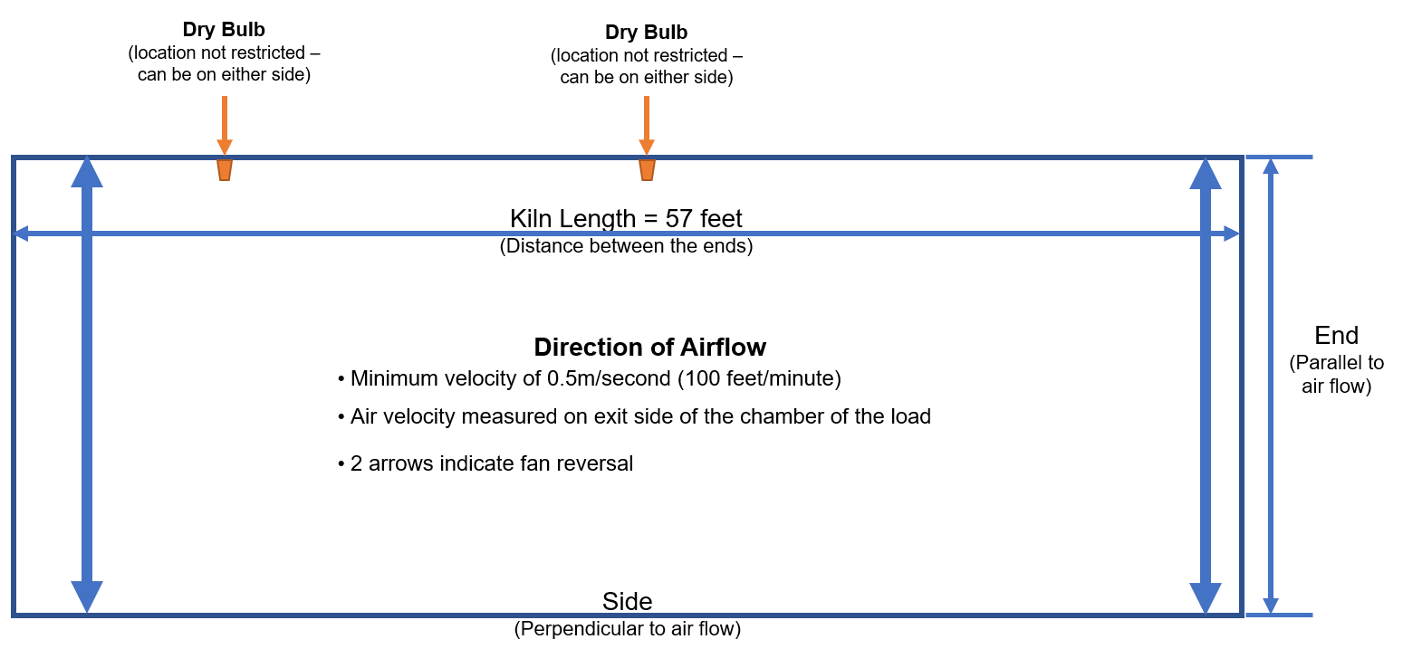
Text description
At the top, positions of the 2 dry bulbs, location is not restricted, and it can be on either side of the chamber. Also, at the top, the kiln length is 57 feet (distance between the ends).
The side length (perpendicular to air flow) is at the bottom. The end (parallel to air flow) is on the right. The direction of the flow is represented by 2 vertical arrows indicating fan reversal. The minimum velocity is 0.5m/second (100 feet/minute), the air velocity is measured on the exit side of the chamber of the load.
For more information, see section 4.5 and 4.9 of this page.
Option D and D1

Text description
At the top, positions of the 2 dry bulbs, location is not restricted, and it can be on either side of the chamber. The kiln length is 57 feet (distance between the ends) and is the same as the side length (perpendicular to air flow)
The end (parallel to air flow) is on the right. The direction of the flow is represented by 2 vertical arrows indicating fan reversal. The minimum velocity is 0.5m/second (100 feet/minute), the air velocity is measured on the exit side of the chamber of the load.
For information, see section 4.6 of this page.
Option P1: Single zone heating chamber with unidirectional airflow (top view)

Text description
Almost at the top, the dry bulb is located central in the chamber on the exit side of the airflow it should be placed as close to or in the load. The wood core probes, minimum two, must be located on the exit side of the airflow in the load.
The end of the chamber (parallel to airflow) is shown at the left with an arrow. The side (perpendicular to airflow) is shown at the bottom and is also described as the chamber's length.
In a single zone heating chamber, the chamber's length must be of 17feet or less. The direction of airflow is shown at the right with an arrow pointing at the top.
Option P1: Single zone heating chamber with bidirectional airflow (top view)

Text description
Almost at the top, one of the dry bulb is located central in the chamber, another dry bulb is shown aligned almost at the bottom on the diagram as dry bulb can be placed on either side.
At least one dry bulb is needed and must be placed as close to or in the load. The wood core probes (minimum 2) are located halfway between the air entry side and the air exit side of the load. The end of the chamber (parallel to airflow) is shown at the left with an arrow.
Beside the end, 2 arrows indicate the halfway of the end. The side (perpendicular to airflow) is shown at the bottom and is also described as the chamber's length.
In a single zone heating chamber, the chamber's length must be of 17 feet or less. The direction of airflow is shown at the right with a bidirectional arrow pointing at the top and the bottom.
Option P1: Multi-zone heating chambers with unidirectional airflow (top view)

Text description
Almost at the top, the position of the dry bulbs, (minimum one per zone) is located in the chamber on the exit side of the airflow.
Dry bulbs should be placed as close to or in the load. The dry bulbs must be at the maximum of 8,5 feet from the ends and the maximum horizontal distance between 2 dry bulb is 24 feet. The wood core probes, minimum one per zone, must be located on the exit side of the airflow in the load. The end of the chamber (parallel to airflow) is shown at the left with an arrow.
The side (perpendicular to airflow) is shown at the bottom and is also described as the chamber's length. This diagram represents a 2-zone heating chamber where each zone is of 17 feet, shown by arrows from the end to the middle.
The chamber's length is 34 feet in this diagram. The direction of airflow is shown at the right with an arrow pointing at the top.
Option P1: Multi-zone heating chambers with bidirectional airflow (top view)

Text description
The dry bulbs (minimum one per zone) is shown at the top but can be located in the chamber on either side and should be placed as close to or in the load. The dry bulbs must be at a maximum of 8,5 feet from the ends and the maximum horizontal distance between 2 dry bulb is 24 feet.
The wood core probes, minimum one per zone, must be located halfway between the sides of the load. The end of the chamber (parallel to airflow) is shown at the left with two bidirectional arrows that meet in the middle to show the half end. The side (perpendicular to airflow) is shown at the bottom and is also described as the chamber's length.
This diagram represents a 2-zone heating chamber where each zone is of 17 feet, shown by arrows from the end to the middle. The chamber's length is 34 feet in this diagram. The direction of airflow is shown at the right with a bidirectional arrow pointing at the top and the bottom.
Option 1: Single heating zone chamber (side view)
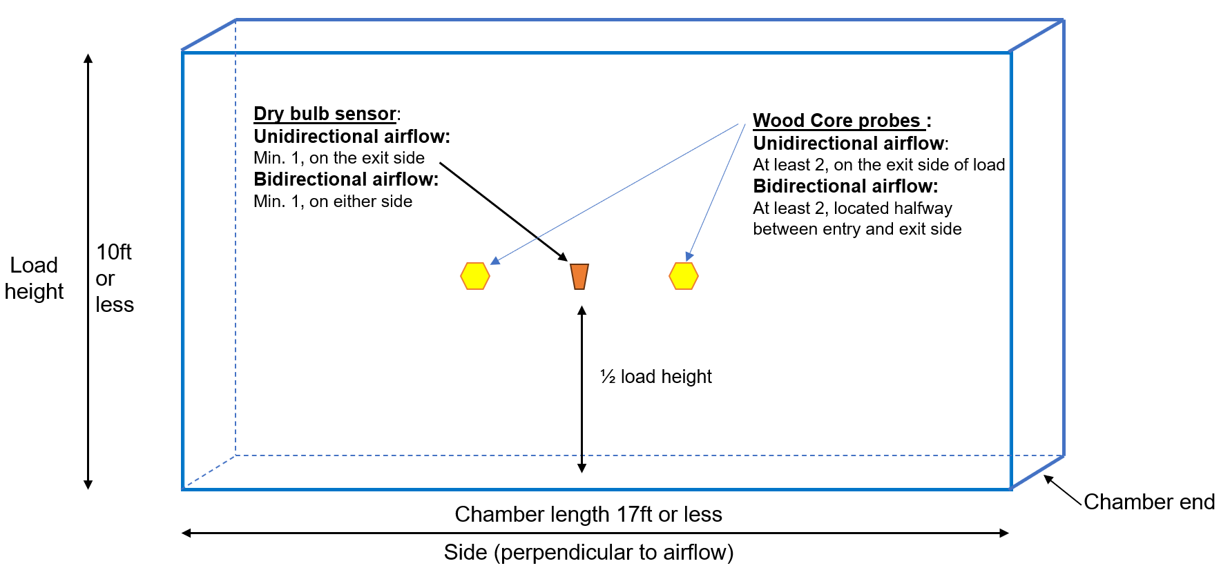
Text description
The diagram shows the vertical aspect of bulb placement in a single zone heating chamber. Dry bulbs and wood core probes must respect the airflow requirements, and, in addition, they must be located vertically about mid zone which represent ½ the load height. The load height is represented by a bidirectional arrow from bottom to top on the left and is of 10 feet or less. The side (perpendicular to airflow) is shown at the bottom and is also described as the chamber's length and is of 17 feet or less in a single zone chamber.
Option P1: Multi heating zone chamber (side view)

Text description
The diagram shows the vertical aspect of bulb placement in a four-zone heating chamber. Dry bulbs and wood core probes must respect the airflow requirements as specified in the muti heating zone chamber diagrams. In addition, they must be located no more than 5 feet from the floor, no more than 5 feet from the top of the load and no more than 10 feet from each other vertically. The load height is represented on the left of the diagram by a bidirectional arrow from bottom to top and is 20 feet high. Two bidirectional arrows of 10 feet each representing the two zones in height. The side (perpendicular to airflow) is shown at the bottom and is also described as the chamber's length and is of 34 feet. or less in a single zone chamber. This diagram represents a 2 zones wide heating chamber where each zone is of 17 feet showed by arrows from the end to the middle.
Option P2

Text description
At the top, position of the wet bulb is in the mid-third of the kiln and it can be on either side of the chamber. The wood core probes are located in each treatment zone in the coldest spot (at mid distance of the air pathway across the load).
The kiln length is 42 feet (distance between the ends), is the same as the side length (perpendicular to air flow) and is represented by an arrow at the bottom of the image.
The end (parallel to air flow) is shown with an arrow on the right.
The direction of the flow is represented by 2 vertical arrows indicating fan reversal. The minimum velocity is 0.5m/second (100 feet/minute), the air velocity is measured on the exit side of the chamber of the load.
For more information, see section 6.3.1 of this page.
Appendix C: diagrams illustrating bi-directional continuous kiln definitions

Appendix C – Text version
Appendix C contains 4 diagrams illustrating the definitions for bi-directional continuous kilns given in section 3.0 for options A, B, B-1-wom and D.
The first diagram illustrates the minimum requirements for option A, B, B-1-wom with 1 wet bulb. At the bottom, the kiln length is separated in 3 segments, the left segment (entering/exiting section) is 60 feet long, the middle segment (main heating section) is 100 feet long, and the right segment (entering/exiting section) is 60 feet long. At the top, track 1 is represented by an arrow that goes from right to left. The heat treatment zone is in the midthird of the main heating section and the ramp-up zone is located on the far right. The heat treatment zone length is 34 feet, and the wet bulb is located within that zone. The ramp-up zone length is 73 feet. The main heating section has been divided in three parts: the first third, the mid third and the last third. At the bottom, track 2 is represented by an arrow that goes from left to right. The ramp-up zone is on left. The heat treatment zone is in the mid third of the main heating section.
The second diagram illustrates the minimum requirements for option A, B, B-1-wom with 3 wet bulbs. At the bottom, the kiln length is separated in 3 segments, the left segment (entering/exiting section) is 60 feet long, the middle segment (main heating section) is 100 feet long, and the right segment (entering/exiting section) is 60 feet long. At the top, track 1 represented by an arrow that goes from right to left. The main heating section has been divided in three parts: the first third, the mid third and the last third The heat treatment zone is in the middle and the ramp-up zone is located on the far right. The heat treatment zone length is 56 feet, and 2 wet bulbs are located within the zone: 1 in the mid third and 1 in the last third. The one in the mid third is used for both tracks. The ramp-up zone length is 73 feet. At the bottom, track 2 is represented by an arrow that goes from left to right. The ramp-up zone is on left. 1 wet bulb is located in the last third of the main heating zone and the heat treatment zone is located in the mid and last third of the main heating section.
The third diagram illustrates the minimum requirements for option A, B, B-1-wom with 4 wet bulbs. At the bottom, the kiln length is separated in 3 segments, the left segment (entering/exiting section) is 60 feet long, the middle segment (main heating section) is 100 feet long, and the right segment (entering/exiting section) is 60 feet long. At the top, track 1 is represented by an arrow that goes from right to left. The heat treatment zone is in the middle and the ramp-up zone is located on the far right. The heat treatment zone length is 56 feet, and 2 wet bulbs are located within the zone: one in the mid third and one the last third. The ramp-up zone length is 73 feet. At the bottom, track 2 is represented by an arrow that goes from left to right. The ramp-up zone is on left. The heat treatment zone and 2 wet bulbs are located in the mid and last third of the main heating zone.
The fourth diagram illustrates the minimum requirements for option D with 2 dry bulbs per track. At the bottom, the kiln length is separated in 3 segments, the left segment is 60 feet long, the middle segment is 100 feet long, and the right segment is 60 feet long. At the top, track 1 is represented by an arrow that goes from right to left. The heat treatment zone is in the middle and the ramp-up zone is located on the far right. The heat treatment zone length is 67 feet, and 2 dry bulbs are located within the zone. The ramp-up zone length is 73 feet. The middle part of the diagram contains the entering/exiting section at each end of the kiln, followed by the last third and first third of the kiln, and the main heating section located in the mid-third of the kiln. At the bottom, track 2 is represented by an arrow that goes from left to right. The ramp-up zone is on right. The heat treatment zone and 2 dry bulbs are the middle.
Appendix D: bi-directional continuous kiln layout diagrams

Appendix D – Text version
Appendix D contains 4 diagrams illustrating the minimum requirements for bi-directional continuous kilns.
The first diagram illustrates the minimum requirements for option A, B and B-1-wom with 1 wet bulb and is entitled Minimum layout requirements for a bi-directional continuous kiln with 1 wet bulb. The kiln length is 220 feet (distance between the ends) and is the same as the side length (perpendicular to air flow) and is represented by an arrow at the bottom of the image. At the bottom, the kiln length is separated in 3 segments, the left segment is 60 feet long, the middle segment is 100 feet long, and the right segment is 60 feet long. The end of the kiln (parallel to air flow) is represented by an arrow at the right of the image. At the top, track 1 is represented by an orange arrow going from right to left in the kiln. The heat treatment zone is in the middle, and there is a ramp-up zone located on the far right. The heat treatment zone length is 34 feet, and the wet bulb is located in the mid-third of the main heating section. The ramp-up zone length is 73 feet (length of 2/3 of the entering/exiting section plus 1/3 of the main heating section). At the bottom, the ramp-up zone is on right, the heat treatment zone is the middle, and track 2 is represented by a green arrow that goes from left to right. The direction of the flow is represented by 2 vertical arrows indicating fan reversal. The minimum velocity is 0.5 m/second (100 feet/minute), the air velocity is measured on the exit side of the chamber of the load. Also see section 4.2.1.2 of this document.
The second diagram illustrates the minimum requirements for option A, B and B-1-wom with 3 wet bulbs and is entitled Minimum layout requirements for a bi-directional continuous kiln with 3 wet bulbs. The kiln length is 220 feet (distance between the ends) and is the same as the side length (perpendicular to air flow) and is represented by an arrow at the bottom of the image. At the bottom, the kiln length is separated in 3 segments, the left segment is 60 feet long, the middle segment is 100 feet long, and the right segment is 60 feet long. The end of the kiln (parallel to air flow) is represented by an arrow at the right of the image. At the top, track 1 is represented by an orange arrow going from right to left in the kiln. The heat treatment zone is in the middle, and the ramp-up zone is located on the far right. The heat treatment zone length is 56 feet (length of the mid-third of the heating section plus distance to the wet bulb), and 1 wet bulb is placed within the exiting of entering third of the main heating section on each track at 22 feet, and another wet bulb is located in the mid-third of the main heating section. The ramp-up zone length is 73 feet (length of 2/3 of the entering/exiting section plus 1/3 of the main heating section). At the bottom, the ramp-up zone is on right, the heat treatment zone is the middle, and track 2 is represented by a green arrow that goes from left to right. The third wet bulb is placed within the exiting or entering third of the main heating section on each track at 22 feet. The direction of the flow is represented by 2 vertical arrows indicating fan reversal. The minimum velocity is 0.5 m/second (100 feet/minute), the air velocity is measured on the exit side of the chamber of the load. Also see section 4.2.1.2 of this document.
The third diagram illustrates the minimum requirements for option A, B and B-1-wom with 4 wet bulbs and is entitled Minimum layout requirements for a bi-directional continuous kiln with 4 wet bulbs. The kiln length is 220 feet (distance between the ends) and is the same as the side length (perpendicular to air flow) and is represented by an arrow at the bottom of the image. At the bottom, the kiln length is separated in 3 segments, the left segment is 60 feet long, the middle segment is 100 feet long, and the right segment is 60 feet long. The end of the kiln (parallel to air flow) is represented by an arrow at the right of the image. At the top, track 1 is represented by an orange arrow going from right to left in the kiln, the heat treatment zone is in the middle, and the ramp-up zone is located on the far right. The heat treatment zone length is 78 feet (distance between wet bulbs), and 1 wet bulb is placed within the main heating section of each track. The ramp-up zone length is 51 feet (length of 2/3 of the entering/exiting section plus distance to wet bulb 1 from entering/exiting section). At the bottom, the ramp-up zone is on right, the heat treatment zone is the middle, and track 2 is represented by a green arrow that goes from left to right. The direction of the flow is represented by 2 vertical arrows indicating fan reversal. The minimum velocity is 0.5 m/second (100 feet/minute), the air velocity is measured on the exit side of the chamber of the load. Also see section 4.2.1.2 of this document.
The fourth diagram illustrates the minimum requirements for option D with 4 dry bulbs and is entitled Minimum layout requirements for a bi-directional continuous kiln with 4 dry bulbs. The kiln length is 220 feet (distance between the ends) and is the same as the side length (perpendicular to air flow) and is represented by an arrow at the bottom of the image. At the bottom, the kiln length is separated in 3 segments, the left segment is 60 feet long, the middle segment is 100 feet long, and the right segment is 60 feet long. The end of the kiln (parallel to air flow) is represented by an arrow at the right of the image. At the top, track 1 is represented by an orange arrow going from right to left in the kiln, the heat treatment zone is in the middle, and the ramp-up zone is located on the far right. The heat treatment zone length is 67 feet (distance from the start of the mid-third of the main heating section). The dry bulb 1 track 1 is located in the first half of the mid-third of the main heating section and the dry bulb 2 track 1 Is located in the second half of the exiting third of the main heating section. The ramp-up zone length is 73 feet (length of 2/3 of the entering/exiting section plus 1/3 of the main heating section). At the bottom, the ramp-up zone is on the left, the heat treatment zone is the middle, and track 2 is represented by a green arrow that goes from left to right. The dry bulb 1 track 2 is located in the first half of the main heating section and the dry bulb 2 track 2 is located in the second half of the exiting third of the main heating section. The direction of the flow is represented by 2 vertical arrows indicating fan reversal. The minimum velocity is 0.5 m/second (100 feet/minute), the air velocity is measured on the exit side of the chamber of the load. Also see section 4.6.1.2 of this document.
Note: When the option prescribes the number and/or locations of bulbs and sensors based on the kiln length, the kiln length is always defined by airflow, regardless of the shape of the kiln.
Appendix E: wood packaging product thickness relative to treatment option selection

Description for figure 1
Figure 1 shows a wood pallet where the air flow is perpendicular to the wood boards on the top of the pallet, through the 2 sections between supporting boards between the top and the bottom of the pallet. In that case, the measure is the thickness of those wood pieces supporting the top and the bottom of the pallet.

Description for figure 2
Figure 2 shows a wood pallet where the air flow is parallel to the wood boards on the top of the pallet, through the 2 sections between the 3 boards at the bottom of the pallet. In that case, the measure is the width of the wood pieces supporting the top and the bottom of the pallet.

Description for figure 3
Figure 3 shows a wood pallet where the air flow is parallel to the wood boards on the top of the pallet, through the 2 sections between the wood blocks between the top and the bottom of the pallet. In that case, the measure is the thickness of the wood blocks supporting the top and the bottom of the pallet.

Description for figure 4
Figure 4 shows a wood pallet where the air flow is perpendicular to the wood boards on the top of the pallet, through the 2 sections between the wood blocks between the top and the bottom of the pallet. In that case, the measure is the width of the wood blocks supporting the top and the bottom of the pallet.